


Table of contents: Removal ↓ Installation ↓
- Move the drive shaft joint up and down, left and right, and axially. Check for binding or looseness.
- If any faults are found, remove the drive shaft, disassemble it or replace it with a new one.
Removal
- Raise and securely support the vehicle.
- Remove the wheel.
Front drive shafts (left and right)
- Remove the wheel speed sensor from the steering knuckle.
- Remove the cotter pin and then unscrew the lock nut from the drive shaft.
- Remove the brake hose retaining plate. Then remove the brake hose from the shock absorber.
- Remove the bolt and nut securing the shock absorber strut to the steering knuckle.
- Using a special puller, remove the drive shaft from the steering knuckle.
The source is published on the portal: www.nissanbook.ru
Caution: When removing the drive shaft, do not tilt the drive shaft joint too much. Do not stretch the inner joint of the drive shaft too much.
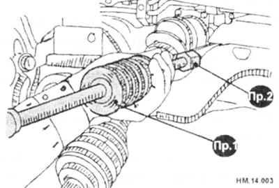
- Remove the drive shaft from the variator as follows.
♦ Install between the drive shaft (from the inner hinge side) and the main transmission, a device for removing the drive shaft (Pr1) and a puller for the drive shaft (Pr2) as shown in the figure.
♦ Remove the drive shaft.
Rear drive shaft
- Remove the wheel speed sensor from the axle.
Caution: Do not pull on the wheel speed sensor wiring harness.
- Remove the cotter pin and then unscrew the lock nut from the drive shaft.
- Remove the parking brake cable and parking brake shoes from the rear plate.
- Unscrew the bolts securing the wheel hub with the bearing, and then remove the wheel hub with the bearing from the shaft.
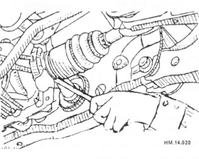
- Using a lug wrench or tire iron, pry the drive shaft out of the final drive.
Installation
- Installation is carried out in the reverse order of removal. Tightening torque for connections: 100-150 Nm.
Caution: When installing, pay attention to the position of the parts and always use new retaining rings, clamps and boots.
Right front shaft
- Install a new snap ring onto the end of the drive shaft and engage the splines of the shaft with the differential gear inside.
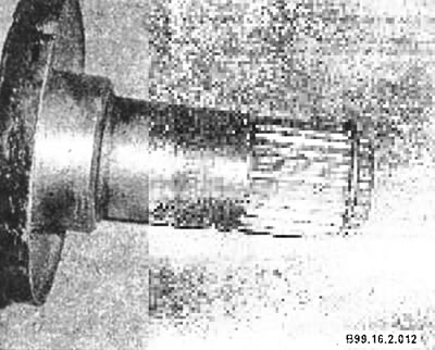
- Press firmly on the shaft until the snap ring fits into the groove inside the differential gear. Once the shaft is engaged, pull sharply on the shaft to ensure the snap ring is securely locked.
Left front shaft and rear shaft
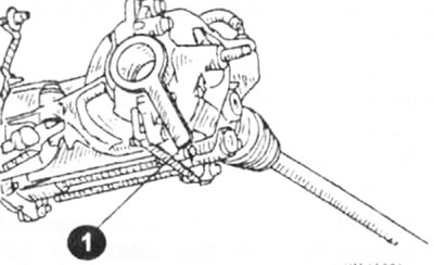
- To prevent damage to the final drive side oil seal, install the guard (1) on the oil seal before installing the drive shaft. Insert the drive shaft into the inner joint and hammer it in to ensure secure installation.
Caution: Make sure the ring clamp is securely fastened.
- Install the new cotter pin and dust boot onto the rear drive shaft.