


Description
Preparation before adjustment
Note: For more details, please refer to the regulations in force in your country.
Adjust the aim of the headlights if repair work has been carried out on the front of the vehicle or additional headlights have been replaced.
Before adjusting the headlight aim, check the following:
- Adjust the pressure in all tires to the correct level
- Fill up with engine coolant, motor oil and fuel.
- Bring the vehicle to an unloaded state. (Remove luggage from the vehicle interior and trunk).
Note: Leave the spare tire, jack and standard tools.
- Wipe off any dirt from the auxiliary lights.
Attention:
- Do not use organic solvents (thinners, gasoline, etc.).
- Place the person in the driver's seat.
Headlight aiming screw
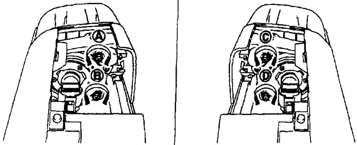
A. Adjusting screw of the right additional headlight (higher/lower); B. Right additional headlight adjusting screw (inside-lower/outside-higher); C. Left additional headlight adjusting screw (higher/lower); D. Left additional headlight adjusting screw (inside lower/outside higher).
| Adjusting screw | Direction of rotation of the screwdriver | Adjustment is in progress | |
| A | Right additional headlight (higher/lower) | Clockwise | Higher |
| Counterclockwise | Below | ||
| IN | Right additional headlight (inward-lower/outward-higher) | Clockwise | Inside-below |
| Counterclockwise | Outward-higher | ||
| WITH | Left additional headlight (higher/lower) | Clockwise | Higher |
| Counterclockwise | Below | ||
| D | Left additional headlight (inside-lower/outside-higher) | Clockwise | Inside-below |
| Counterclockwise | Outward-higher | ||
Headlight aiming adjustment procedure
1. Install the screen.
Note:
- Stop the car at a right angle to the wall.
- Place the screen perpendicular to the road.
2. Stop the car at a right angle to the screen so that the distance between the centers of the additional headlights and the screen is 10 m.
3. Start the engine and turn the headlight switch to the "2ND" and "H1" positions. And press the additional headlight button.
Note: Block the light from the additional headlight that is not adjusted with a thick cloth, etc. so that it does not fall on the wall screen.
Caution: Do not cover the surface of the diffuser with tape, as it is made of plastic.
4. Adjust the headlight beam direction using the adjusting screws so that the center point of the intense light area on the screen is within the adjustment area.
Unit of measurement, mm
| Headlight beam adjustment section | |
| In the vertical direction (Y) (down from the center line of the additional headlights) | In the horizontal direction (X) (to the right/left of the center line of additional headlights) |
| 0-174 | Within 174 |
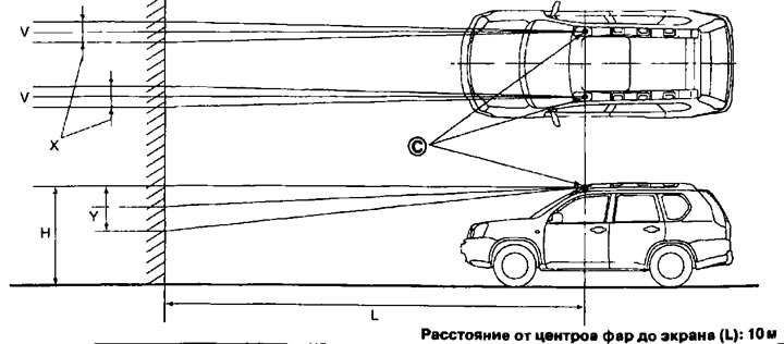
C. Center of additional headlight; V. Vertical center line of additional headlights; H. Horizontal center line of additional headlights; X. Headlight beam adjustment section (horizontally); Y. Headlight beam adjustment section (vertically).