


Table of contents: Removal and installation ↓ Post-installation check ↓
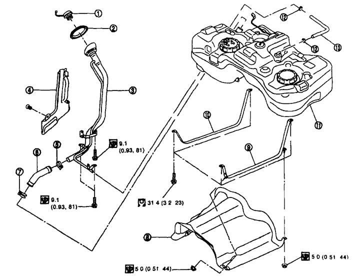
Fuel tank 1. Fuel tank filler cap; 2. Rubber bushing; 3. Filler neck pipe; 4. Lid; 5. Clamp; 6. Filler neck hose; 7. Clamp; 8. Fuel tank protection; 9. Fuel tank strap (left); 10. Fuel tank strap (right); 11. Fuel tank; 12. Clamp; 13. Ventilation hose.
Removal and installation
Removal
1. Perform operations 2-7 p. "Removal" ("Fuel level sensor, fuel filter and fuel pump assembly") higher.
2. If necessary, drain the fuel from the fuel tank. See above.
(The source is published on the portal: «www.nissanbook.ru»)
Attention:
- Since the fuel tank tilts forward and becomes unstable during removal/installation, any remaining fuel should be drained.
- Stop the vehicle on a level, firm surface.
3. Remove the main muffler. See below.
4. Remove the driveshaft. See chapter "Power transmission (on 4WD models)".
5. Remove the fuel tank protection.
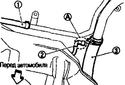
6. Disconnect the ventilation hose (1) from the rear of the fuel tank.
7. Disconnect the EVAP pipe (2) from the rear of the fuel tank.
- See above for instructions on how to remove the EVAP tube quick disconnect fitting (A).
8. Disconnect the filler neck hose (3) from the filler neck pipe side.
9. Remove the suspension rod. See chapter "Rear axle and suspension (on 4WD models)".
10. Loosen the parking brake cable mounting bolts and separate the cable from the suspension arm. See Chapter "Brake system (on 4WD models)".
11. Disconnect the connector from the 4WD solenoid valve (on 4WD models).
12. Loosen the final drive mounting nut (A) on the rear suspension beam (1). See Chapter "Rear axle and suspension (on 4WD models)".
Caution: Do not loosen the final drive mounting nut.
13. Remove the final drive mounting bolts (B) from the final drive mounting bracket (3) and tilt the final drive assembly (2). See Chapter "Power transmission (on 4WD models)".
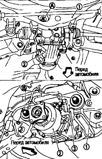
Note: It is not necessary to remove the final drive assembly from the vehicle.
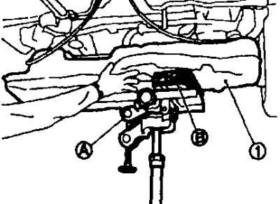
14. Support the central part of the fuel tank (1) with a telescopic support (A).
Caution: Place a wooden block (B) between the telescopic strut and the fuel tank.
15. Remove the fuel tank strap clamps on the right and left.
16. Supporting the fuel tank with your hands, carefully lower the telescopic stand and remove the tank.
Caution: The fuel tank may be unstable due to the shape of its bottom. Do not rely on the telescopic stand. Support the tank securely with your hands.
Installation
Installation is carried out in the reverse order of removal, taking into account the following.
Filler neck hose.
- Place the hose onto the pipe to a depth of 35 mm and secure with a clamp.
- Make sure the hose clamp does not sit on the thickened part (bead) of the fuel line.
- Tighten the fuel hose clamp so that the distance from the end of the hose is:
From the filler neck pipe side: 7-11 mm
From the fuel tank side: 5-9 mm
EVAP hose
1. Check that there is no damage to the joints and that no foreign particles have gotten into them.
2 Center the nipple with the hose, then insert the nipple at a right angle until it clicks into place.
3. After connecting, make sure the connection is secure by pulling the quick-release fitting with your hand and (central fuel line under the bottom)
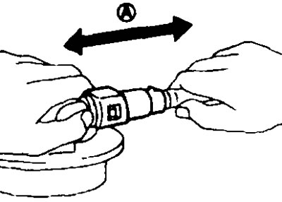
A. Pull
Post-installation check
Check for fuel leaks as follows:
1. Turn the ignition key to the "ON" position (without starting the engine). After creating pressure in the fuel lines, check for fuel leaks at the joints.
2. Start the engine. Increase the engine speed and check again for fuel leaks at the joints of the fuel lines and hoses.