


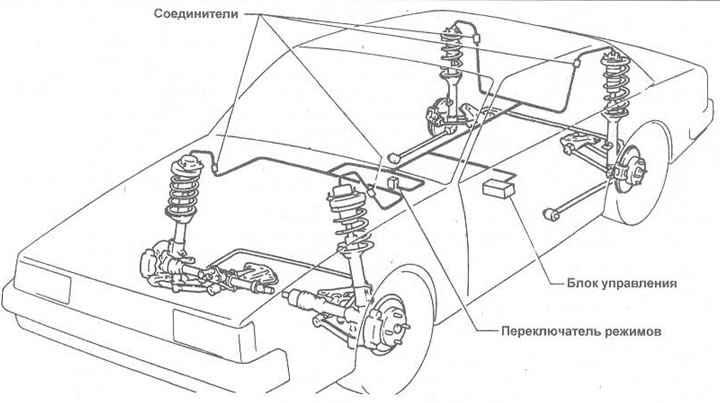
Figure 12.15. Location of electrical components of the suspension damping adjustment system
1. The electrical circuit consists of a selector switch, a control unit and four actuators mounted on top of each suspension strut.
2. The circuit is powered from the battery through a fusible link and the ignition relay to a fuse (labeled "Turn Signal/Transmission").
3. The control unit is installed under the driver's seat, which must be removed before carrying out work.
4. Each actuator is removed and installed as described in the relevant Chapters.
5. To remove the switch, remove it from the panel and disconnect the electrical wiring.
6. In addition to the light that comes on whenever the light is turned on, the switch is equipped with three LEDs.
7. The LEDs also act as self-monitoring for the control unit. If more than one LED lights up at the same time or blinks, check the entire circuit, first checking the battery and all connectors.
8. If all LEDs are known to be good, then turn off the ignition and replace the switch. If the LEDs still do not light, first check the fuse, then check the power supply in the control unit.
9. Check the harness connecting clamp of the control unit for breakage 11 (green wire) and ground. The criterion for the serviceability of this circuit is the presence of voltage between the terminals of block 1 and 11 (the voltmeter is connected with the negative probe to terminal 11, the positive to terminal 1 with the ignition on). If there is no voltage, check the wiring harness until damage is found. If power is supplied, the switch is faulty and must be replaced.
10. If two LEDs are lit, turn off the ignition and replace the switch with another unit, then turn on the ignition again. If the switch now works properly, check the wiring.
11. If all three LEDs are lit, turn off the ignition and connect the switch to another installation, then turn on the ignition again. If there is no change, check the switch as described in the previous paragraph, and replace it if it is faulty.
12. If one LED is constantly on and the other two are blinking, first turn off the ignition and perform maintenance work on the system in compliance with safety precautions. If the damage is not repaired when the ignition is turned on, then the fault is either in the control unit or one of the actuators.
13. If the damage is in the control unit or one of the actuators, the car must be serviced at a specialized Nissan station. The faulty units must be replaced.