


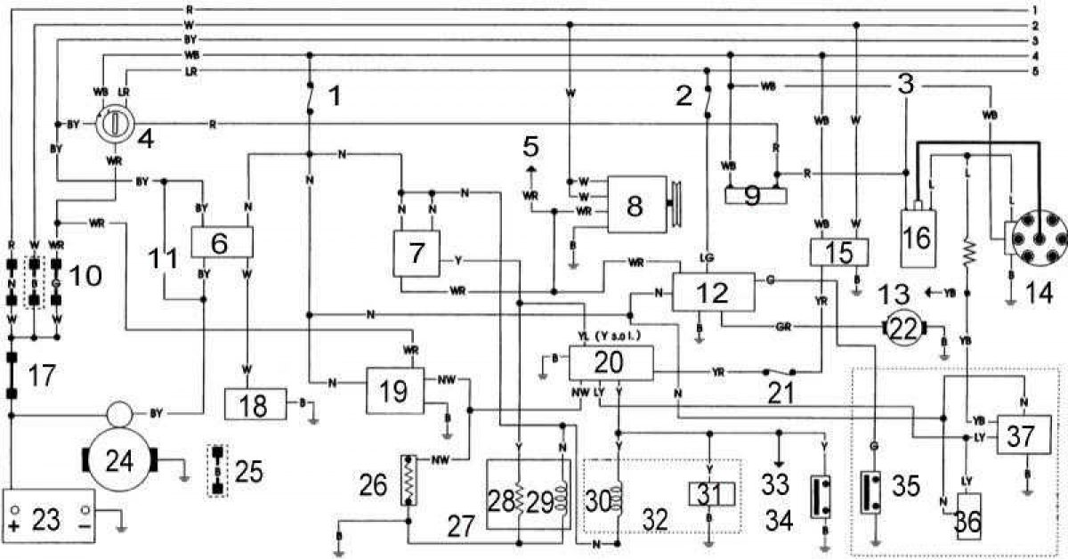
Electrical connection diagram for starting, charging, engine electrical equipment and emission control systems
Open a larger image in a new tab »
1 - Engine electrical circuit fuse; 2 - fuel pump circuit fuse; 3 - 3.0L models only; 4 - ignition switch; 5 - to the combined meter; 6 - relay of the start enable switch-diode; 7 - automatic start relay; 8 - generator; 9 - resistor (4.2L models only); 10 - fuse links; 11 - Manual transmission; 12 - fuel pump control unit (3.0L models only); 13 - to the tachometer; 14 - distributor; 15 - ignition relay; 16 - coil; 17 - main fuse link (only 4.2L models produced since October 1994.); 18 - Start permission switch sensor; 19 - heater relay (3.0L models only) 20 - control connector; 21 - meter fuse; 22 - fuel pump; 23 - battery; 24 - starter; 25 - fuse link (4.2L models only, discontinued October 1994.); 26 - heater with positive temperature component (3.0L models only); 27 - carburetor; 28 - automatic start; 29 - solenoid fuel shut-off valve; 30 - solenoid valve (BCDD); 31 - speed sensor switch; 32 - manual transmission only; 33 - to the combined meter; 34 - Start permission switch sensor; 35 - oil pressure switch; 36 - fuel return solenoid valve (3.0L models only); 37 - engine speed block
For wiring color codes on this wiring diagram, see here →