


Table of contents: Checking and adjusting the alignment…↓ Wheel alignment - front wheels ↓ Toe-in adjustment - rear wheels ↓ Checking and adjusting the front…↓
1. Accurate wheel alignment ensures good handling and performance, prevents excessive tire wear. Before adjusting, check that the tires are in good condition and inflated to the specified pressure, the wheels are not deformed, the steering gear and suspension are in good condition, without play or wear. The car must be parked on a flat horizontal surface with a net weight.
2. Wheel installation includes five dimensions:
Collapse - the angle of deviation of the wheel axis from the vertical line, when viewed from the front or rear of the vehicle. Positive camber is the angle (in degrees), when the top edge of the wheel is tilted outward from the vehicle; negative camber is when the top edge of the wheel is tilted inward. Camber is not adjustable.
Longitudinal inclination of kingpin - the angle between the kingpin axis and a vertical line when viewed from each side of the vehicle. Positive caster - the top end of the kingpin axis is tilted toward the rear of the vehicle. Kingpin caster is not adjustable.
Transverse inclination of kingpin - the angle between a vertical line through the front or rear wheel and a line through the center of the upper strut mount and the center of the lower control arm ball joint, viewed from the front or rear of the vehicle. The lateral tilt is not adjustable.
Wheel alignment - the difference in distances between the front inner edges of the wheel rims and the rear inner edges of the wheel rims, measured at the height of the hub. If the distance at the front is less than the distance at the rear, the wheels have "positive toe-in." If the opposite is true, the wheels have "divergence." On the front wheels, positive toe-in is adjusted by changing the length of the steering rods, while on the rear wheels, it is adjusted by changing the length of the rear (adjustable) transverse balancers.
Rotation angles - the difference in steering angles between the inner and outer front wheels, measured at the maximum steering angle. The main adjustment is made by changing the length of the steering column lock bolts on the hub mounting element.
Checking and adjusting the alignment - front and rear wheels
3. For accurate control, the car must be at net weight, the tire pressure must be correct, the car must be on a horizontal surface. Rock the car to adjust the suspension, check that the wheels are in the straight-ahead position. The steering wheel must be in neutral.
4. Move the car back a few steps, then forward.
5. First measure the distance between the inner edges of the wheel rims, at the height of the center of the hub on the rear side of the wheels; record the measurement "A". Now push the car forward so that the wheels turn exactly 180° (half a turn) and measure the distance again, but now at the height of the center of the hub on the front side of the wheels; record the measurement "B". The measurement would be more accurate if it were repeated several times at points spaced 120° around the inner side surface of the wheel rim and the resulting measurements were averaged.
6. To determine the front toe-in, refer to Figure 10.38 and subtract measurement "B" from measurement "A". To determine the rear toe-out, subtract measurement "A" from measurement "B". The resulting value should be within the specified range.
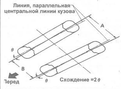
Figure 10.38. Calculating convergence: Positive convergence (front wheels) =A-B; Discrepancy (rear wheels) = B-A
7. If adjustment is required, see below.
Wheel alignment - front wheels
8. Check that both steering rods are installed as shown in Figure 10.39.
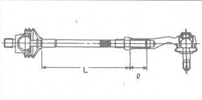
Figure 10.39. Basic installation values of the steering rod: Length of the right side L = 177.9 mm; Length of left side L = 178.4 mm; Lengths of both sides I = 25 mm minimum
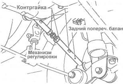
Figure 10.40. Rear wheel alignment components
9. Loosen the locknuts of the outer ball joints of the steering rods.
10. Evenly change the length of both steering rods by screwing them into the outer ball joints (to reduce positive toe-in) or by twisting their external ball joints (to increase positive toe-in). Change the setting by a quarter turn, check the toe as described above and repeat the adjustment if necessary.
11. After adjustment, tighten the locknuts of the outer ball joints of the steering rods to the tightening torque specified in Specifications if possible.
Toe-in adjustment - rear wheels
12. Before adjusting, check the installation of both rear (adjustable) transverse balancers (Figure 10.41).
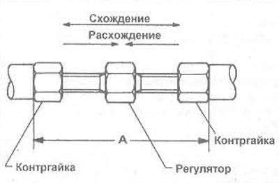
Figure 10.41. Basic installation values of the rear (adjustable) balancers: Length A-50-55mm.
13. Loosen both adjuster locknuts on each balancer completely. Do not allow the balancer to rotate on the bushing.
14. Change the length of both cross balancers by the same amount by screwing the adjusters (to shorten the balance beam and increase the divergence) or by turning the regulators (to reduce the discrepancy). Change the setting by a quarter turn, check the discrepancy and repeat the adjustment if necessary.
15. After adjustment, tighten all locknuts to specification torque if possible.
Checking and adjusting the front wheel steering angles
16. Turn the steering wheel first in one direction until the outer wheel has turned 20°, check the turning angle of the inner wheel. Then turn the steering wheel back through the neutral position and repeat the measurement.
17. Turn the steering wheel to the maximum angle, measure the angles. On vehicles with power steering, start the engine and set the idle speed, apply a force of 98-147 N using a spring balance attached to the steering wheel rim, measure the angles. Turn the steering wheel in the opposite direction until it stops, repeat the measurement.
18. If the corners are not set correctly, check that the steering column lock bolts are installed as shown in Figure 10.42; the plastic bolt cover is in good condition. Loosen the lock nuts.
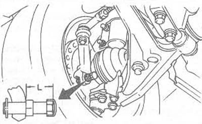
Figure 10.42. Basic installation values of the front wheel steering angle lock bolt: Turbo Models L = 31 mm; All other models L = 24 mm
19. Both bolts must be installed evenly. On T12 and early T72 Turbo models with power steering, check that the spacers are installed correctly at each end of the strut.