


Table of contents: Description ↓ Preliminary check ↓ Checking the camber angles,…↓ Checking with a caliper for…↓ Checking wheel alignment ↓
Description
Attention:
- The camber, longitudinal and transverse tilt angles of the steering axis cannot be adjusted.
- If the camber, caster and lateral tilt angles of the steering axis deviate from the norm, check the front suspension components. If necessary, replace damaged or worn parts.
- The transverse tilt angle of the pivot axis is a reference value and does not require verification.
Measure the front wheel alignment angles when unloaded.
Note: Unladen condition means full fuel, coolant and engine oil. Spare tire, jack, tools and mats in their proper places.
Preliminary check
Check the following:
- is the tire pressure normal and is there any wear?;
- road wheel beating;
- axial play in wheel bearings; see above;
- axial play in the ball joint of the transverse arm; see above;
- work of the rack;
- is there any play or deformation in the places where the axle and suspension are attached?;
- are there any cracks, deformations or other damages on the suspension beam and wishbone;
- height of an unloaded vehicle.
Checking the camber angles, longitudinal and transverse tilt angles of the wheel steering axis
- The camber and lateral tilt angles of the steering axis are not subject to adjustment.
- Before checking, roll the car with the front wheels on the steering angle measuring gauge. Place a stand of the same height under the rear wheels so that the car is in a horizontal position.
Checking with a caliper for measuring camber, caster and lateral inclination of the steering axis (CCK)
Secure the SSC caliber (special tool: KV991040S0) on the wheel as follows and take measurements:
1. Remove the three wheel nuts and screw the guide bolts onto the hub studs.
2. Screw the adapter into the plate until it is pressed firmly against it.
3. Screw the center plate into the plate.
4. Insert the plate assembly onto the guide bolt. Place the spring on it, then tighten the nuts evenly on the three guide bolts. Do not compress the spring completely when tightening the nuts.
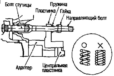
5. Place the concave part of the wheel alignment gauge against the convex part of the center plate, press firmly and take the measurement.
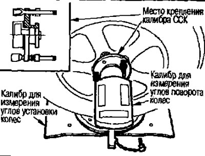
Camber, caster and camber angles: See below under "Technical data and specifications".
Attention:
- If the camber, caster and lateral tilt angles of the steering axis are different from the norm, check the front suspension components. If necessary, replace damaged or worn parts.
- The transverse tilt angle of the pivot axis is a reference value and does not require verification.
Checking wheel alignment
Measure the wheel alignment as follows:
Attention:
- Always take measurements on a level surface.
- Before rolling the car, make sure there is no one in front of it.
[The source of the article is on the website: www.NissanBook.ru]
1. Rock the front of the car to stabilize the suspension.
2. Roll the vehicle straight forward for approximately 5 m.
3. Place a mark (A) at the tread baseline (rear) of both wheels at the height of the hub center. These marks will be the measurement points.
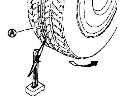
4. Measure the distance "A" (from the back).
5. Slowly roll the car forward so that the wheels turn 180°(1/2 turn).
Note: If the wheels have turned more than 180° (1/2 turn) take the measurement first. Do not roll the car backwards.
6. Measure the distance "B" (from the front side).
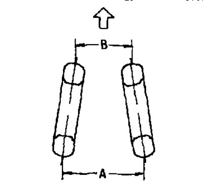
Overall toe-in A - B Overall toe-in: See below under "Technical data and specifications".
If the toe-in is different from the norm, adjust by changing the length of the outer and inner steering rods.