


Table of contents: Removal ↓ Installation ↓ Disassembly ↓ Assembly ↓ Check after removal ↓ Checking after disassembly ↓
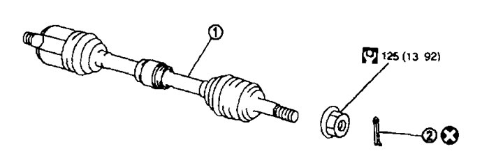
Removal from the left side 1. Drive shaft; 2. Cotter pin.
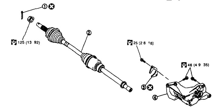
Removal from the right side 1. Cotter pin; 2. Drive shaft; 3. Plate; 4. Support bearing bracket.
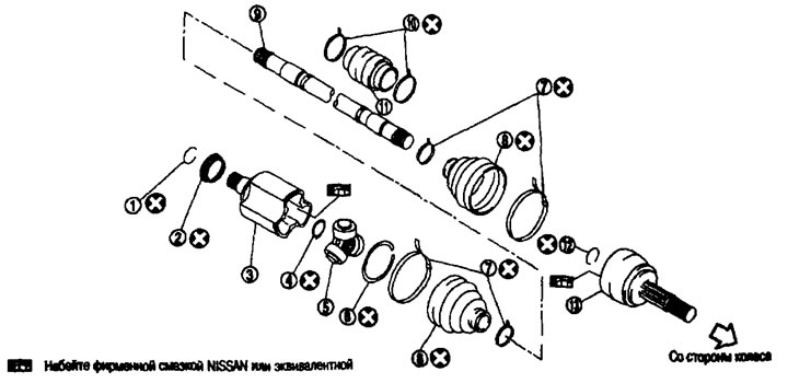
Disassembly from the left side 1. Ring clamp; 2. Dust cover; 3. Body; 4. Retaining ring; 5. Crosspiece assembly; 6. Retaining ring; 7. Cover clamp; 8. Cover; 9. Shaft; 10. Dynamic shock absorber clamp; 11. Dynamic shock absorber; 12. Ring clamp; 13. Hinge assembly.
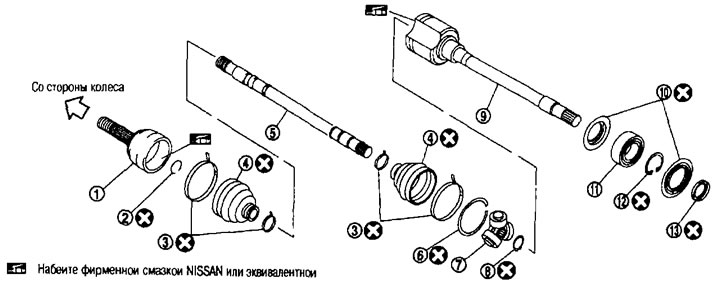
Disassembly from the right side 1. Hinge assembly; 2. Ring clamp; 3. Cover clamp; 4. Cover; 5. Shaft; 6. Retaining ring; 7. Crosspiece assembly; 8. Retaining ring; 9. Body; 10. Dust cover; 11. Thrust bearing; 12. Retaining ring; 13. Dust cover.
Removal
On the left side
1. Perform operations 1-11 of the "Replacement" item above.
2. Remove the drive shaft from the gearbox assembly.
Remove using attachment (A) to drive shaft (special tool KV40107500) and an impact puller (B) by inserting the tip of the attachment between the housing and the gearbox.
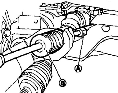
Caution: Do not bend the drive shaft joint to a large angle when removing the drive shaft. Also, do not overstretch the sliding joint.
On the right side
1. Perform operations 1-11 of the "Replacement" item above.
2. Unscrew the plate bolts and remove the plate.
3. If necessary, loosen the support bearing bracket mounting bolts and remove the bracket.
4. Remove the drive shaft from the gearbox assembly.
- Remove using a drive shaft attachment (special tool KV40107500) and an impact puller, inserting the tip of the attachment between the housing and the gearbox.
Caution: Do not bend the drive shaft joint to a large angle when removing the drive shaft. Also, do not overstretch the sliding joint.
Installation
On the left side
Installation is carried out in the reverse order of removal, taking into account the following:
Attention:
- When installing the drive shaft, always replace the differential seal. See chapter "Continuously variable transmission (CVT)".
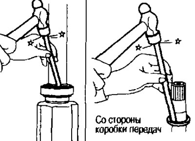
- To avoid damaging the seal when installing the drive shaft, install the guard (A) (special tool; KV381079000) to the gearbox.
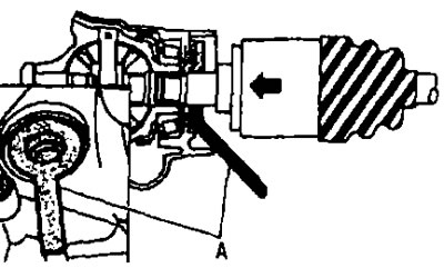
- Insert the drive shaft sliding joint and tap it securely with a hammer.
Caution: Make sure the ring clamp is fully engaged.
On the right side
Installation is carried out in the reverse order of removal, taking into account the following:
Caution: Always replace the differential seal when installing the drive shaft. See chapter "Continuously variable transmission (CVT)".
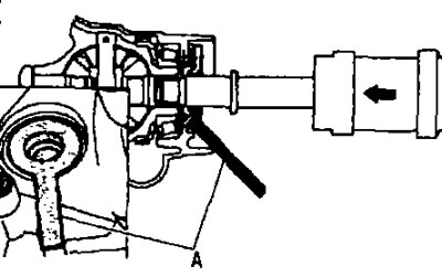
- To avoid damaging the oil seal when installing the drive shaft, install the guard (A) (special tool KV381079000) to the gearbox.
- Insert the drive shaft sliding joint and tap it securely with a hammer.
- When installing the support bearing bracket (1).
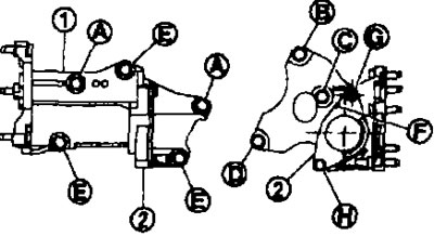
- Tighten the mounting bolts by hand in order (A).
- Tighten the mounting bolts in the order (B), (C), (D), (E), (A).
- Place the plate (2) so that the cutout (F) is on top. Tighten the mounting bolts by hand in the order (G), (H).
Caution: Do not reuse the plate.
Disassembly
From the gearbox side
1. Secure the shaft in a vice.
Caution: When clamping the shaft in a vice, protect it from damage by placing aluminum or copper strips.
2. Remove the clips from the case, then remove the case from the body.
3. Remove the retaining ring.
4. Apply alignment marks to the housing and shaft, then remove the housing from the shaft.
Caution: Mark with paint or similar substance. Do not scratch surfaces.
5. Place alignment marks (A) on the crosspiece assembly and shaft.
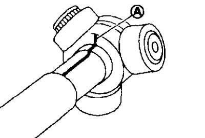
Caution: Mark with paint or similar substance. Do not scratch surfaces.
6. Remove the retaining ring (1), then remove the crosspiece assembly from the shaft.
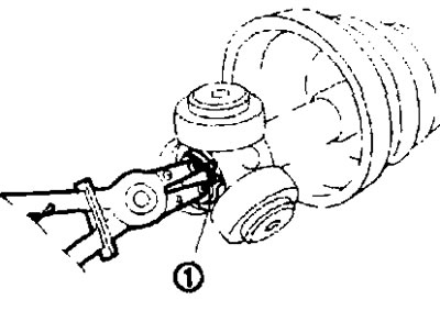
7. Remove the cover from the shaft.
8. Remove the ring clamp from the shaft (on the left side).
9. Remove the dust cover from the housing.
10. Remove old grease from the body with paper towels.
Thrust bearing
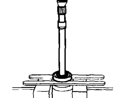
1. Remove the dust cover from the housing.
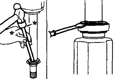
2. Remove the retaining ring.
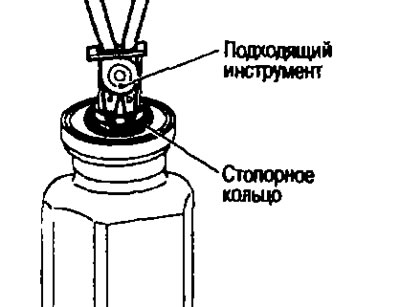
3. Press the support bearing out of the housing.
4. Remove the dust cover.
Dynamic shock absorber
Remove the clamps, then remove the dynamic shock absorber from the shaft.
From the wheel side
1. Secure the shaft in a vice.
Caution: When clamping the shaft in a vice, protect it from damage by placing aluminum or copper strips.
2. Remove the clips from the boot, then remove the boot from the hinge assembly.
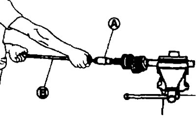
3. Thread the drive shaft puller (A) onto the threads of the joint assembly at least 30 mm and remove the joint assembly from the shaft using the impact puller (B).
Attention:
- If the pivot assembly cannot be removed even after 5 attempts, replace the shaft and pivot assembly as a set.
- Align the impact puller and drive shaft and remove using right angle force.
4. Remove the ring clamp from the shaft.
5. Remove the cover from the shaft.
6. Remove old grease from the hinge assembly with paper towels by rotating the collar.
Assembly
From the gearbox side
1. To avoid damaging the boot, wrap the splined portion of the shaft with electrical tape (A). Place the new boot on the shaft and secure with clamps.
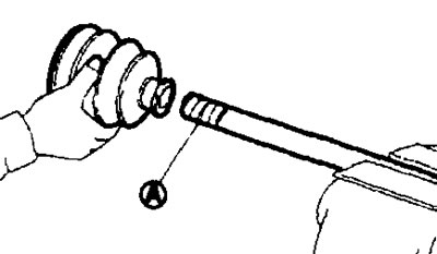
Caution: Do not reuse the cover and clips.
2. Remove the electrical tape wrapped around the splined portion of the shaft.
3. Align the marks (A) applied to the shaft (2) when removing the crosspiece (1). Install the crosspiece assembly with the splined part (B) towards the drive shaft.
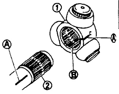
4 Secure the crosspiece assembly to the shaft with the retaining ring (1).
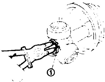
Caution: Do not reuse the retaining ring.
5. Apply the required amount of grease to the crosspiece assembly and sliding surface.
6. Install the housing onto the crosspiece assembly and apply grease to the amount specified below.
Standard.
Amount of grease: See below. "Technical data and specifications".
7. Align the marks made when removing the housing.
8. Install the retaining ring.
Caution: Do not reuse the snap ring.
9. Firmly fix the cover into the grooves (marked with "*") as shown in the figure.
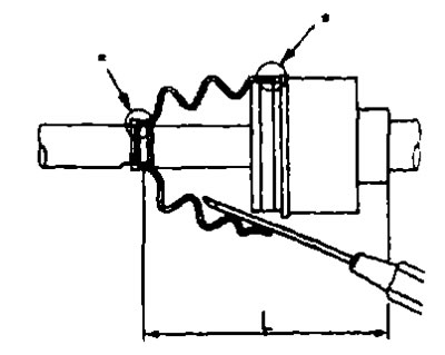
Caution: If grease gets into the boot mounting surfaces (marked with "*") on the shaft or housing, the boot may come off. Remove all grease from the surfaces.
10. To avoid deformation of the cover, bring the cover installation length to the required value ("L") specified below by inserting a flat-head screwdriver or similar tool under the cover from the wide side and releasing air from it.
Standard.
Length of the installation of the chakhla ("L"): See below. "Technical data and specifications".
Attention:
- If the installation length of the cover is different from the standard, the cover may break.
- Do not touch the tip of the screwdriver to the inside surface of the case.
11. Securely fasten the wide and narrow sides of the cover with new clips as shown in the picture.
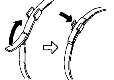
Caution: Do not reuse the cover clips.
12. Secure the housing and shaft, then make sure they are in the correct position by rotating the boot. If not, reinstall them by installing new boot clamps.
13. Install the dust cover (on the left side).
Caution: Do not reuse the dust cover.
14. Install the ring clamp onto the body (on the left side).
Caution: Do not reuse the ring clamp.
Thrust bearing
1. Install the dust cover on the body.
Caution: Do not reuse the dust cover.
2. Press the support bearing onto the housing.
3. Install the retaining ring.
Caution: Do not reuse the retaining ring.
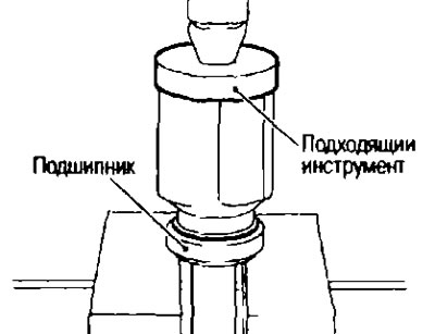
4. Install the dust covers.
Caution: Do not reuse dust caps.
Dynamic shock absorber
If the dynamic shock absorber is removed, secure it with new clamps as shown in the figure so that the dimensions correspond to those indicated below.
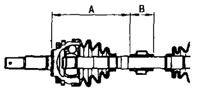
Caution: Do not reuse the case clips.
Standard.
Size: See below. "Technical data and specifications".
From the wheel side
Perform the assembly following the operations in paragraph. "Replacing the drive shaft cover" higher.
Check after removal
- Move the hinge up/down, left/right and axially. Make sure the movement is smooth and there is no significant play.
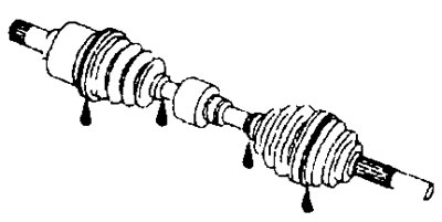
- Check the covers for cracks, damage and leaks.
- If there are any abnormalities, remove the drive shaft and replace the faulty components.
Checking after disassembly
Shaft
Check the shaft for runout, cracks or other damage. Replace if necessary.
Dynamic shock absorber
Check for cracks or wear. Replace if necessary.
Hinge assembly (from the wheel side).
Check the following:
- Does the hinge assembly rotate freely and is there excessive axial play?.
- Have any foreign particles entered the hinge assembly?.
- Are there any cuts, cracks or breaks inside the hinge assembly?.
- If any deviation from the norm is detected, replace the hinge assembly.
- Body and crosspiece assembly (from the gearbox side).
- If there are scratches or wear on the contact surface under the rollers on the housing or crosspiece side, replace the housing and crosspiece assembly.
Note: The housing and crosspiece assembly are replaced as a set.
Thrust bearing (on the right side)
Make sure the wheel bearing rotates freely. Check for knocking, cracking, pitting or wear. If there are any abnormalities, replace the support bearing.
Thrust bearing bracket (on the right side).
Check for any bending, cracks or damage. If any, replace the support bearing bracket.