


Removal
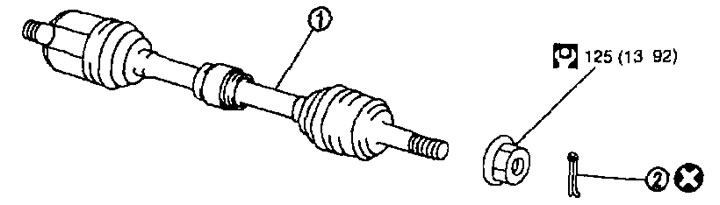
On the left side. 1. Drive shaft; 2. Cotter pin.
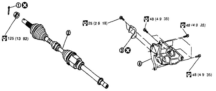
On the right side (mR20DE engine) 1. Cotter pin; 2. Drive shaft; 3. Plate; 4. Support bearing bracket.
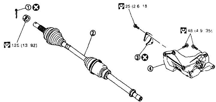
On the right side is the QR25DE model. 1. Cotter pin; 2. Drive shaft; 3. Plate; 4. Support bearing bracket.
Disassembly
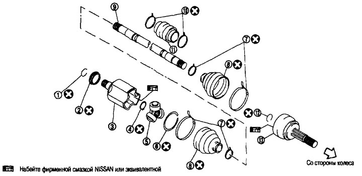
On the left side (mR20DE and QR25DE engines). 1. Ring clamp; 2. Dust cover; 3. Body; 4. Retaining ring; 5. Crosspiece assembly; 6. Retaining ring; 7. Cover clamp; 8. Cover; 9. Shaft; 10. Dynamic shock absorber clamp (engine QR25DE); 11. Dynamic shock absorber (engine QR25DE); 12. Ring clamp; 13. Hinge assembly.
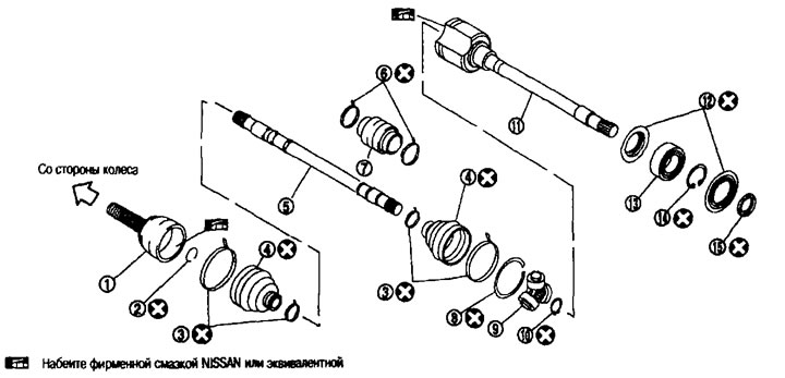
From the head of the party (mR20DE and QR25DE engines). 1. Hinge assembly; 2. Ring clamp; 3. Cover clamp; 4. Cover; 5. Shaft; 6. Dynamic shock absorber clamp (mR20DE engine); 7. Dynamic shock absorber (mR20DE engine); 8. Retaining ring; 9. Crosspiece assembly; 10. Retaining ring; 11. Body; 12. Dust cover; 13. Thrust bearing; 14. Retaining ring; 15. Dust cover.
Replacement
From the wheel side
1. Remove the wheels from the vehicle.
2. Remove the wheel sensor from the steering knuckle. See chapter "Brake system".
Caution: Do not pull on the wheel sensor wiring.
3. Remove the locking plate from the stand. See chapter "Brake system".
4. Remove the mounting bolts from the caliper bracket. Hang the caliper bracket so that it does not interfere with your work. See Chapter "Brake system".
Caution: Do not press the brake pedal after removing the brake caliper.
5. Remove the brake disc.
Attention:
- Before removing the brake disc, make alignment marks on the brake disc and on the wheel hub and wheel bearing assembly.
- Do not drop the brake disc.
6. Remove the cotter pin, then loosen the hub lock nut.
7. Separate the wheel hub and wheel bearing assembly from the drive shaft by lightly tapping the end with a hammer, placing a wooden block underneath, then unscrew the hub lock nut.
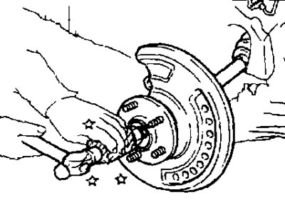
Attention:
- Do not bend the drive shaft joint to a large angle. Also, do not overstretch the sliding joint.
- Do not allow the drive shaft to hang without support from the housing (or hinge assembly), shaft and other components.
Note: If the wheel hub cannot be separated from the drive shaft after following the above procedure, use a suitable puller.
8. Separate the wishbone from the steering knuckle.
9. Loosen the outer tie rod end nut.
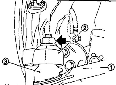
10. Using a ball joint puller, remove the outer tie rod end (1) from the steering knuckle (2) being careful not to damage the ball joint boot (3).
Caution: To avoid damaging the threads and the ball joint puller coming off, tighten the nut by hand.
11. Remove the drive shaft from the wheel hub and wheel bearing assembly.
12. Remove the clips from the boot, then remove the boot from the hinge assembly.
13. Thread the drive shaft puller (A) onto the threads of the joint assembly at least 30 mm. Supporting the drive shaft with one hand, remove the joint assembly from the shaft using the impact puller (B).
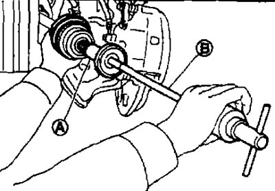
Attention:
- Align the impact puller and drive shaft and pull using firm, even pressure.
- If the joint assembly cannot be removed, try again after removing the drive shaft from the vehicle.
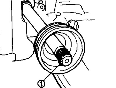
14. Remove the ring clamp (1) from the shaft (mR20DE and QR25DE engines).
15. Remove the cover from the shaft.
16. Wipe off old grease from the hinge assembly with paper towels.
17. Pack NISSAN genuine grease or equivalent into the spline hole of the ball joint assembly (1) until the spline hole and the groove of the ball joint are filled to the brim.
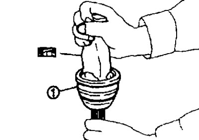
Caution: After applying the lubricant, wipe off the old leaked lubricant with a napkin.
18. To avoid damaging the cover, wrap the splined part of the shaft (mR20DE and QR25OE engines) with electrical tape (A). Place the new cover on the shaft and secure with clamps.
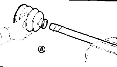
Caution: Do not reuse the cover and clips.
19. Remove the electrical tape wrapped around the splined portion of the shaft.
20. Place the ring clamp (1) into the groove on the end of the shaft.
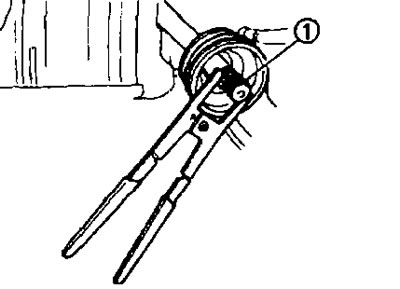
Caution: Do not reuse the ring clamp.
Note: It is recommended to install the ring clamp using a mounting jig.
21. Align the shaft and the hinge assembly. Then insert the shaft with the ring clamp into the hinge assembly.
22. Install the hinge assembly (1) onto the shaft (mR200E and QR25OE engines) using a plastic hammer.
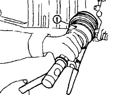
Caution: When turning the drive shaft, make sure that the hinge assembly is properly engaged.
23. Bring the amount of lubricant to the required level by stuffing it into the cover from the inside, on the wide side of the cover.
Standard.
Amount of grease. See below. "Technical data and specifications".
24. Secure the cover tightly into the grooves (marked with a label), as shown in the figure.
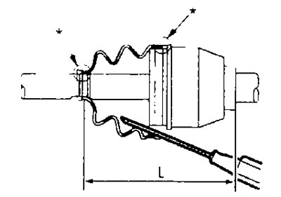
Caution: If grease gets on the boot mounting surfaces (marked with "*") on the shaft or on the hinge assembly, the boot may come off. Remove all grease from the surfaces.
25. To avoid deformation of the cover, bring the cover installation length to the required value ("L") indicated below by inserting a flat-head screwdriver or similar tool under the cover from the wide side and releasing air from it.
Standard.
Cover installation length ("L"). See below. "Technical data and specifications".
Attention:
- If the installation length of the cover is different from the standard, the cover may break.
- Do not touch the inside surface of the case with the tip of the screwdriver.
26. Using the tool for crimping the clamps of the covers (A) (special tool: KV40107300), secure the wide and narrow sides of the cover with new clamps.
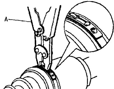
Note: Fix the clamp so that the dimension "M" is equal to the one shown below.
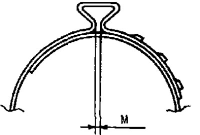
Size "M" 1.0-4.0 mm.
27. Secure the hinge assembly and shaft, then check that they are in the correct position by rotating the boot. If not, reinstall them by installing new boot clamps.
28. Insert the drive shaft into the wheel hub and wheel bearing assembly, then tighten the hub lock nut by hand.
Caution: The drive shaft has a press-fitted gasket. When inserting the shaft, do not push it, but pull it by tightening the hub lock nut until it is completely seated.
29. Install the wishbone onto the steering knuckle. See below.
30. Install the outer tie rod end onto the steering knuckle. See Chapter "Steering".
31. Install the brake disc.
Caution: If you reuse the brake disc, align the marks made during removal.
32. Install the caliper bracket onto the steering knuckle. See Chapter "Brake system".
33. Install the locking plate on the stand. See chapter "Brake system".
34. Install the wheel sensor on the steering knuckle. See chapter "Brake system".
35. Tighten the hub lock nut to the specified torque.
36. Install the cotter pin.
Attention:
- Do not reuse the cotter pin.
- To avoid play, simply bend the cotter pin at the base.
37. Install the wheels on the car.