


Side of the ear
1. Remove the wheels from the car.
2. Remove the wheel speed sensor from the steering knuckle.
Caution: Do not pull the wheel sensor wire.
3. Remove the locking plate from the suspension strut assembly.
4. Loosen the suspension arm mounting bolts and use your hands to move the arm so that it does not interfere with the work.
Caution: Do not press the brake pedal when the brake caliper is removed.
5. Remove the brake disc.
6. Remove the cotter pin and unscrew the wheel hub lock nut.
7. Place a wooden block on the hub lock nut. Tap the wooden block with a hammer to disengage the wheel hub with the bearing assembly from the drive shaft. Remove the hub lock nut.
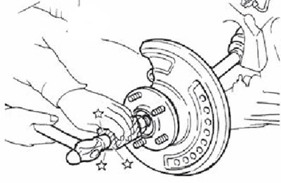
Attention.
- Avoid bending the drive shaft joint at a large angle. Also avoid excessive stretching of the spline connection.
- Do not allow the drive shaft to fall due to lack of support from the joint, shaft or other parts.
Note: If the wheel hub does not come off even after following the above procedure, a suitable puller must be used.
8. Remove the cotter pin (1) of the outer steering joint and unscrew the nut.
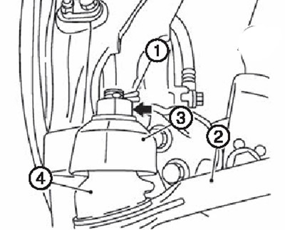
9. Remove the outer steering joint (2) from the steering knuckle (3) using a special puller so as not to damage the ball joint boot (4).
Caution: Temporarily tighten the nut to prevent damage to the threads and accidental slipping of the ball joint puller.
10. Remove the transverse steering rod from the steering knuckle.
11. Remove the drive shaft from the wheel hub with the bearing assembly.
12. Remove the boot clamps and then the boot itself from the constant velocity joint (CV joint) assembly.
13. Screw the drive shaft puller (A) into the threaded part of the CV joint by at least 30 mm. Supporting the drive shaft with one hand, use the impact puller (B) to remove the CV joint assembly from the shaft.
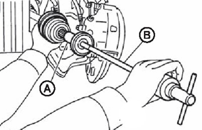
Attention.
- Align the breaker bar with the drive shaft and remove by pulling evenly and firmly.
- If the CV joint assembly cannot be removed, remove it after removing the drive shaft from the vehicle.
14. Remove the snap ring (1) from the shaft (except for versions with M9M engine) or assembled housings (version with M9R engine).
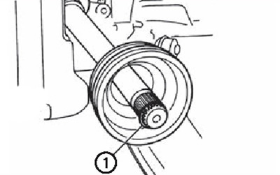
15. Remove the boot from the shaft.
16. Use paper towels to remove old grease from the constant velocity joint assembly.
17. Fill the joint slots (1) to the brim with genuine NISSAN grease or equivalent.
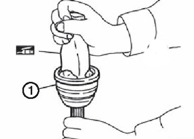
Caution: After adding grease, remove any remaining old grease with a rag.
18. Wrap the shaft splines (except for versions with M9R engine) or assembled housings (version with M9R engine) with insulating tape (A) to protect the boot from damage. Install the boot with clamps on the shaft.
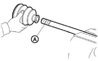
Caution: Do not reuse the boot with clamps.
19. Remove the electrical tape from the shaft splines.
20. Place the snap ring (1) into the groove on the end of the shaft.
Caution: Do not reuse the snap ring.
Note: It is recommended to install the snap ring using a special tool.
21. Align the end of the shaft with the constant velocity joint assembly. Then connect the shaft to the joint using the snap ring.
22. Install the constant velocity joint assembly (1) onto the shaft (except for versions with M9R engine) or the housing assembly (M9R) using a plastic hammer.
The article was copied from here: nissanbook.ru
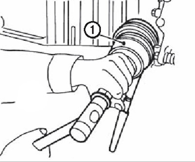
Caution: Rotate the shaft to ensure that the constant velocity joint assembly is seated correctly.
23. Add the required amount of grease (see "Service data and specification" at the end of the chapter) inside the boot from the side of the larger diameter of the boot.
24. Insert the boot securely into the grooves (are marked with asterisks in the figure).
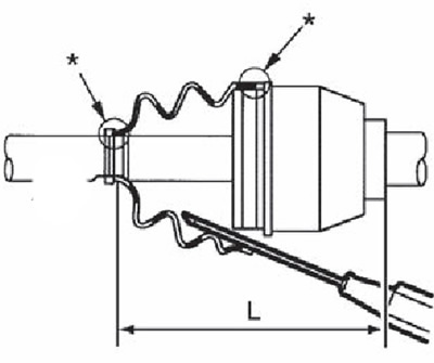
Caution: If grease gets on the mounting surfaces of the boot (are marked with asterisks in the figure) on the shaft or in the constant velocity joint assembly, the boot must be removed and all grease must be removed from the surfaces.
25. To prevent deformation of the boot, adjust its installation length to the set value L (see "Service data and specification" at the end of the chapter) by inserting a suitable tool inside the anther from the larger diameter side of the anther and releasing air from the inside.
Attention.
- If the installation length of the boot exceeds the standard, the boot may be damaged.
- Be careful not to touch the inside surface of the boot with the tip of the tool.
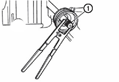
26. Secure the large and small ends of the boot with clamps using a special crimping tool (A) (KV40107300).
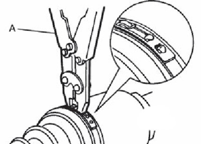
Note: Fix the boot clamp so that the dimension M shown in the figure is 1.0-4.0 mm.
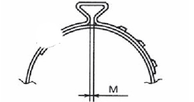
27. Having fixed the constant velocity joint assembly and the shaft relative to each other, make sure that the boot is installed correctly. If necessary, reinstall the boot correctly.
28. Insert the drive shaft into the wheel hub with the bearing and tighten the lock nut.
Attention. The drive shaft has an interference fit. When installing the shaft, do not apply excessive force, but simply seat it in place, tightening the lock nut.
29. Install the transverse steering rod onto the steering knuckle.
30. Install the outer steering joint onto the steering knuckle.
31. Install the brake disc.
32. Install the suspension arm onto the steering knuckle.
33. Install the locking plate onto the suspension strut assembly.
34. Install the wheel speed sensor on the steering knuckle.
35. Tighten the wheel hub lock nut to the specified tightening torque (see the relevant section above).
Z6. Install the cotter pin.
Attention.
- Do not reuse the cotter pin.
- Bend the ends of the cotter pin to ensure that the lock nut does not loosen.
37. Install the wheels on the car.