Removing
1. Remove the wheels from the car.
2. Remove the wheel speed sensor from the steering knuckle.
Attention. Do not pull on the wheel sensor wire.
3. Remove the lock plate from the suspension strut assembly.
4. Unscrew the suspension arm mounting bolts and move the arm with your hands so that it does not interfere with work.
Attention. Do not press the brake pedal with the brake caliper removed.
5. Remove the brake disc.
6. Loosen and unscrew the locknut of the wheel hub.
7. Place a piece of wood on the hub locknut. Tap the block of wood with a hammer to remove the wheel hub and bearing assembly from the drive shaft. Remove the hub locknut.
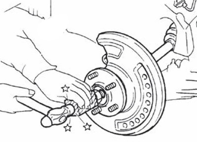
Attention.
- Avoid bending the drive shaft joint at a large angle. Also, do not overstretch the spline connection.
- Do not allow the drive shaft to fall due to lack of support for the pivot, shaft, or other parts.
Note. If the wheel hub does not come off even after following the above procedure, a suitable puller must be used.
8. Remove cotter pin (1) outer steering joint and unscrew the nut.
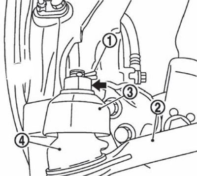
9. Remove the outer steering joint (2) with rotary knuckle (3) using a special puller so as not to damage the boot of the ball joint (4).
Attention. Temporarily screw on the nut to prevent damage to the threads and accidental slippage of the ball joint extractor.
10. Remove the tie rod from the steering knuckle.
11. Remove drive shaft from wheel hub with bearing assembly.
12. Right side only:
- Loosen the screws and remove the plate.
- If necessary, loosen the mounting bolts and remove the support bearing bracket.
13. Remove the drive shaft from the gearbox assembly:
Insert end of special tool (A) (KV40107500) with puller (IN) between housing and gearbox assembly.
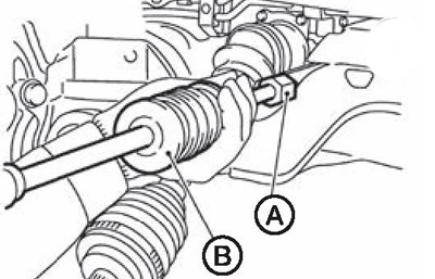
Attention. Avoid bending the drive shaft joint at a large angle. Also, do not overstretch the spline connection.
Installation
Installation is carried out in the reverse order of removal, taking into account the following:
Replace the differential side seal with a new one each time the drive shaft is installed.
Place protective device (A) (KV38107900) on the gearbox assembly to prevent damage to the oil seal when installing the drive shaft. Insert drive shaft splines and tap lightly with a hammer to secure.
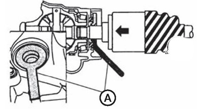
Left-hand side
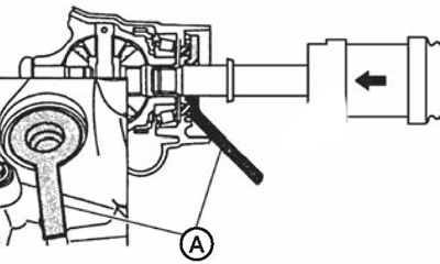
Right side
Attention. Make sure the retaining ring is secure.
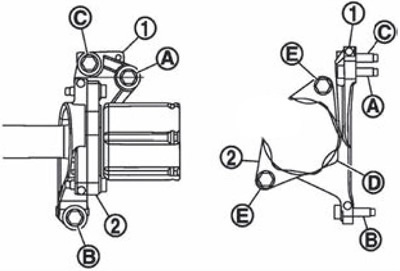
Except for versions with M9R engine: when installing the thrust bearing bracket (1) install the mounting bolts in sequence (A), (IN); install plate (2) so that the groove (WITH) was on top, screw on the fastening bolts in the e sequence (A), (b).
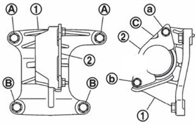
Version with M9R engine: when installing the thrust bearing bracket (1) fasten mounting bolts (A), (IN) and tighten the bolts in sequence (WITH), (A), (IN).
Install the bearing housing (2) so that the ledge (D) was on the front side of the car, then tighten the bolt (E).