


Table of contents: Repair of the right shaft of a car…↓ Replacing the thrust bearing ↓
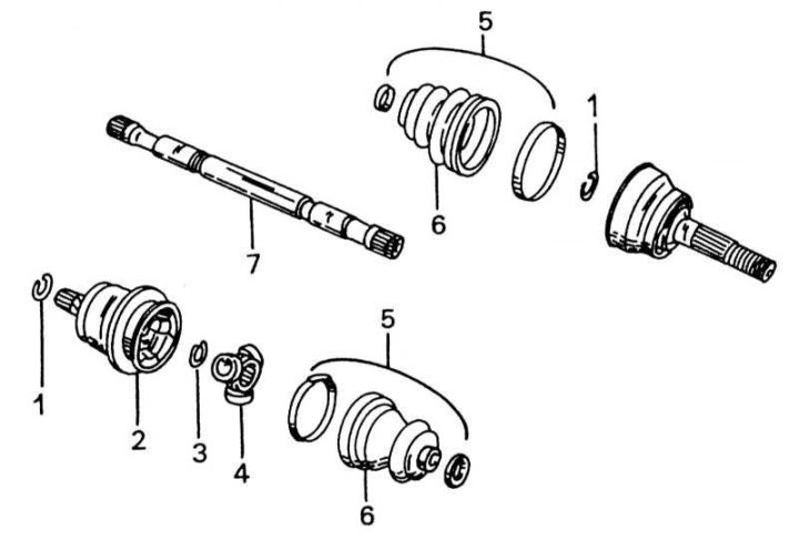
Details of a disassembled drive shaft with a sprocket joint inside
1 - retaining ring; 2 - internal constant velocity joint; 3 - retaining ring; 4 - joint star; 5 - rubber cuff tightening bands; 6 - rubber cuff; 7 - drive shaft
The constant velocity joint on the wheel side, as well as the ball joint of the right shaft of a car with an injector, cannot be disassembled. Only the rubber seals can be replaced. The inner constant velocity joint of the left shaft of an injector engine, as well as both shafts of a carburetor engine, can be repaired as described below. It is also possible to disassemble the thrust bearing to replace the ball bearing located there, if it is broken.
When disassembling the tripod joint, proceed as follows, guided by illustration:
1. Clamp the drive shaft in a vice and remove both rubber cuff clamp bands. The clamp bands can be discarded immediately.
2. Mark the position of the hinge housing relative to the drive shaft and remove from the end of the shaft.
3. While holding the drive shaft in a vice as shown in the illustration, mark the sprocket and shaft with paint.
4. Remove the retaining ring (3) from the end of the shaft (7). Discard the retaining ring immediately.
5. Place the drive shaft under the press so that the hinge is flush with the press table and press the shaft out of the sprocket. Hold the shaft from below, otherwise it will fall down.
6. Remove the rubber seal from the shaft. Clean all parts and inspect thoroughly. The joint sprocket is not disassembled and should be replaced as a set if the needle roller bearing is broken. Check the splines inside the joint sprocket for wear before reinstalling the part. When assembling the drive shaft, proceed as follows:
7. Place a new small clamp on the shaft of the new seal.
8. Clamp the drive shaft in a vice using blocks.
9. Place the joint sprocket on the shaft in accordance with the markings (illustration below). If a new sprocket is used, this does not matter. The sprocket has a grip on the inside of one side, and this side must be put on the shaft first.
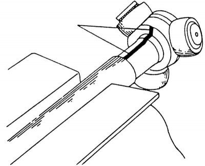
Before removing the tripod joint, mark the shaft and joint with paint.
10. Tap the joint sprocket onto the shaft with a light metal hammer and insert a new retaining ring (3). The rounded side of the retaining ring faces the sprocket.
11. Now fill the joint with grease. Depending on the car model, the amount of grease varies. For a shaft of a car with a 1.6 L engine, the amount of grease is 175-185 g; on all other vehicles 205-215 g. Press grease into the joint and install the cuff.
12. Install the large clamp and pull it tight. Then bend the end so that it fits between the staples and bend both staples onto the tape.
13. Stretch the cuff until it is size "L" (see illustration below) on a car with a 1.6L engine will not be equal to 89-91 mm or on other cars 96-98 mm. Place the small clamp in the same way.
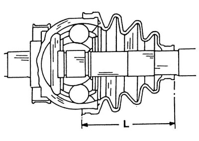
Stretch the cuff on the gearbox side until the "L" dimension matches the value in the text.
14. Depicted on illustrations constant velocity joint of the drive shaft (bierfield hinge) can be replaced as follows:
15. If the joint needs to be replaced, remove the ABS toothed rotor from the shaft.
16. After loosening both clamps, slide the joint sleeve back on the shaft.
17. Remove the retaining ring (8) from the groove using special pliers. Discard the retaining ring immediately, as it should not be used a second time.
18. Mark the installation position of the joint on the shaft with a felt-tip pen and remove the joint from the shaft. If the joint needs to be replaced, it can be knocked off with a hammer while holding the shaft in a vice. Otherwise, it should be carefully knocked off with a light metal hammer.
19. Clean the drive shaft thoroughly and clamp the shaft in a vice again.
20. Place the rubber seal on the shaft with the large hole facing out.
21. Place the joint on the shaft. If the same parts are used, the marks must be aligned again.
22. Thread the old drive shaft nut on until the end is flush and tap the joint onto the shaft with a light metal hammer until the snap ring on the inside can be snapped in with a pair of needle nose pliers.
23. Fill the joint with the required amount of grease. On a car with a 1.6 L engine, the amount of grease is 80-110 g, on other engines 110-130 g.
24. Install the large clamp and pull it tight. Then bend the end so that it lies between the brackets and bend both brackets.
25. Stretch the cuff until its length reaches the specified value (see illustration).
26. Fasten the small clamp in the same way. Check that both clamps are seated properly.
Repair of the right shaft of a car with an injection engine
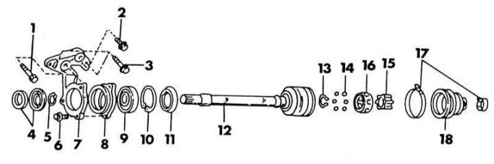
Individual parts of the drive shaft with thrust bearing
1 - bolt, 30-40 Nm; 2 - bolt, 25-35 Nm; 3 - bolt, 45-60 Nm; 4 - dust ring; 5 - retaining ring; 6 - bolt, 16-19 Nm; 7 - support console; 8 - thrust bearing housing; 9 - ball bearing; 10 - retaining ring; 11 - dust protection ring; 12 - intermediate shaft; 13 - retaining ring; 14 - balls; 15 - inner bearing race; 16 - separator; 17 - cuff clamps; 18 - cuff
[The material is taken from a web resource: NissanBook.ru]
The outer joint of this shaft has the same design as shown in illustrations. This also applies to the shaft. The end of the shaft (7) is not in a tripod joint, but in a ball joint. The illustration above shows additional parts of such a shaft, which is guided by a thrust bearing.
1. Remove the sealing bands and clean the inside of the shaft and joint from grease. If the shaft and joint are to be reassembled, (for example, when replacing the cuff), mark the connection appropriately.
2. Clamp the shaft firmly in a vice and tap the joint with a light alloy hammer as shown in the illustration below. Hit at different points around the circumference.
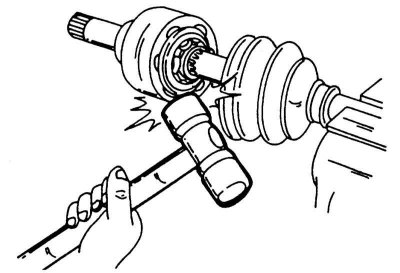
Knocking down the constant velocity joint.
3. Remove the hinge and remove the rubber cuff.
4. Wrap the end of the shaft with adhesive tape and put the cuff with a small clamp on the shaft.
5. Fill the joint with 175-185 g of grease and install the cuff. At the small end, the cuff should sit well in the groove, as shown in the illustration. Tighten both clamps of the cuff well and fix it by bending the brackets.
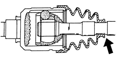
The cuff should fit snugly in the groove at the location indicated by the arrow.
Replacing the thrust bearing
The thrust bearing must first be unscrewed from its mounting before it can be disassembled.
1. Knock the outer dust cover off the shaft using a rod. Dust rings (4) (see illustration) will be filmed together.
2. Using a screwdriver, remove the dust ring (11) from the bearing housing and open and remove the retaining ring underneath using special pliers.
3. Place the bearing housing under the press and press out the shaft.
4. Knock out the bearing (9) from the housing. Reassemble in the reverse order. Carefully tap in the dust rings on both sides with a small mandrel, being careful not to damage them.