


2. Unscrew the screws and remove the distributor runner.
3. Remove the support plate (photo).
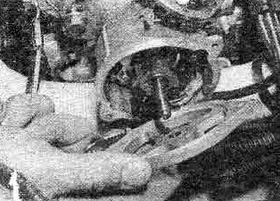
4.3. Removing the metal support plate
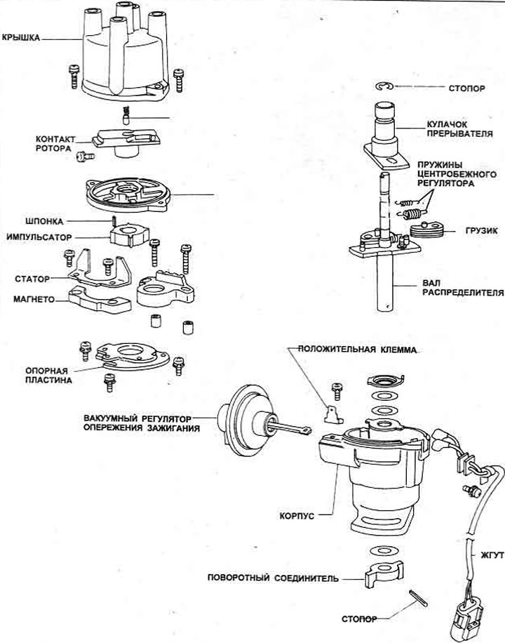
Figure 4.3. Ignition distributor Hitachi D4R83, D4R85 and D4R87 - models with carburetor
4. Mark the position of the pulse generator, remove the cylindrical pin and remove the pulse generator from the shaft.
5. Unscrew the two screws and remove the stator and magnet.
6. Loosen the wiring harness support screw on the distributor housing (photo). Disconnect the harness.
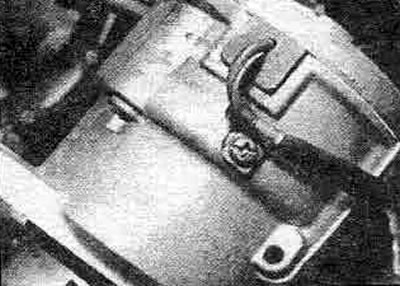
4.6. Distributor Wiring Harness and Holder Screw
7. Unscrew the two screws and remove the integrated ignition unit. Remove the gaskets.
8. Where installed, remove the screw securing the vacuum regulator rod to the support plate.
9. Remove the three screws and lift up the support plate assembly while disengaging the vacuum regulator control lever.
10. Mark the position of the coupling on the cotton wool.
11. Drive out the roll pin and remove the sleeve and thrust washer.
12. Remove the shaft from the housing, noting the position of the thrust washers.
13. Loosen the screw and remove the vacuum regulator, noting the location of the ground clamp.
14. Mark the position of the runner axle relative to the secondary shaft, then remove the upper E-clamp, axle, weights and adjuster springs.
15. Clean and check all components, replace any worn or damaged ones.
16. Carefully wipe the distributor cap, check for cracks or burnt black lines from the high-voltage contact of the spark plugs. Replace the cap if any damage is found.
17. Check that the resistance between any two terminals is at least 50 megohms (Figure 4.4). Check the length of the brushes, replace them if necessary.
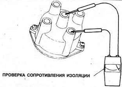
Figure 4.4. Checking the insulation of the breaker-distributor cover
18. Assembly is carried out in reverse order.
19. Lubricate the pivot points of the governor weight, governor spring, rotor axle, support plate assembly, vacuum regulator rod and the working surface of the support plate bearing.
20. When installing the regulator weights, install the small springs first, then the large ones (Figure 4.5).
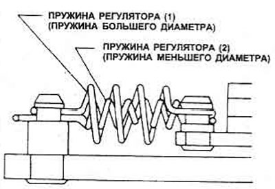
Figure 4.5. Installing the regulator weight springs
21. Place the rotor shaft on the driven shaft as shown in Figure 4.6.
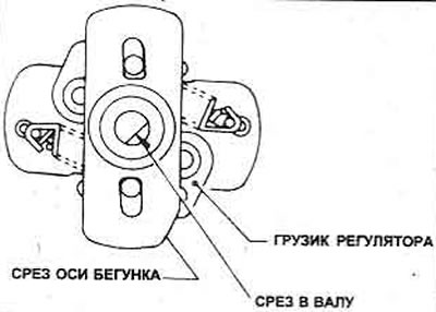
Figure 4.6. Correct positioning of the runner axis on the driven shaft of the distributor
22. Place the support plate, aligning it with the marks (Figure 4.7).
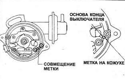
Figure 4.7. Alignment of distributor support plate marks
23. When installing the pulser on the rotor axis, place the cylindrical pin as shown in Figure 4.8.
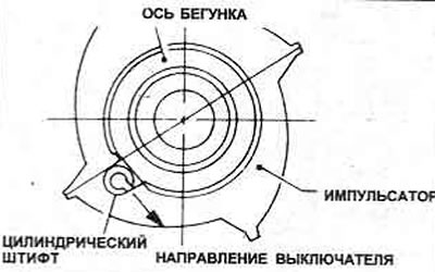
Figure 4.8. Correct positioning of the cylindrical pin in the pulse generator
24. Install the distributor on the vehicle.
25. If necessary, rotate the engine until the two opposite protrusions on the impulse generator are aligned with the two stator blades.
26. Use a feeler gauge to check that the air gap between the protrusions and the blades is within the specified tolerance (Figure 4.9).
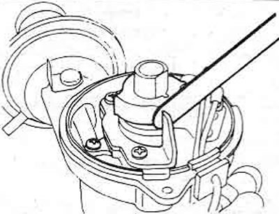
Figure 4.9. Checking the air gap of the pulser/stator
(The source is published on the portal: «nissanbook.ru»)
27. If adjustment is necessary, loosen the two stator screws, move the stator, and retighten the screws.
28. Install the support plate, distributor runner and distributor cover, check the ignition timing.