


Table of contents: Case ↓ Steering gear housing assembly ↓ Outer and inner tie rod ends ↓ Ball joint swing moment ↓ Axial play of ball joints ↓
Case
Check for cracks. Replace if necessary.
Steering gear housing assembly
Check for damage and scratches (on the inner walls). Replace if necessary.
Outer and inner tie rod ends
Check the following parameters. If they are different from the norm, replace the corresponding component.
Ball joint swing moment
Hook the dynamometer at the point shown in the figure and pull it. Make sure that the reading at the moment the ball joint tip and the inner tie rod end begin to move is within the normal range. If the reading is different from the normal range, replace the outer and inner tie rod ends.
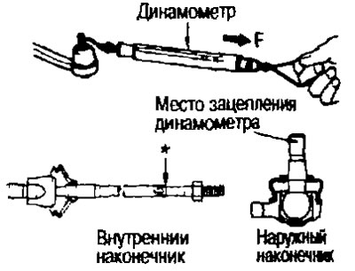
Standard values for the outer tip.
(The measurement point is the hole for the cotter pin on the tip).
- Swinging moment: See below section "Technical data and specifications".
- Dynamometer measurement: See below section "Technical data and specifications".
Standard values for the internal tip.
(Measuring point at distance "*" as shown in the figure)
- Swinging moment: See below section "Technical data and specifications".
- Dynamometer measurement: See below section "Technical data and specifications".
Axial play of ball joints
Apply a load of 490 N (50 kg) to the ball joint tip in the axial direction. Using a dial indicator, measure the amount of movement that the tip makes. Make sure that the reading is within the standard range specified below. If the value is not within the standard range, replace the outer (1) and inner (2) tie rod ends.
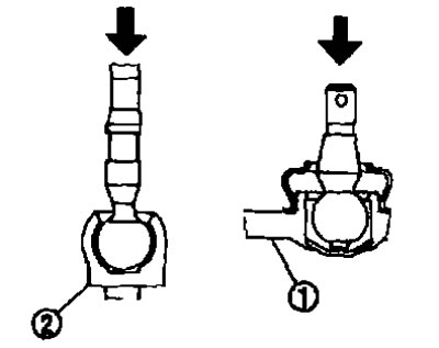
Standard:
- External tip: See below section "Technical data and specifications".
- Inner tip: See below section "Technical data and specifications".