


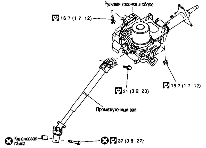
Removal and installation
Removal
Attention:
- When removing, do not allow the steering column assembly to be struck in the axial direction.
- Before removing the intermediate shaft, apply alignment marks to the intermediate shaft and steering column assembly.
- Do not turn the steering wheel when the vehicle is stopped, as the electric motor and EPS control unit may overheat.
- Be careful when crushing the steering column assembly from the vehicle, as it is heavier.
- Do not expose the steering column assembly to magnetism.
- The steering column cannot be disassembled.
1. Set the front wheels to the straight-ahead position.
2. Adjust the steering column to its maximum height.
3. Remove the steering wheel. See above.
4. Remove the cover from the steering column. See chapter "Interior and exterior body equipment".
5. Remove the spiral wire.
6. Remove the combination switch. See chapter "Electrical equipment".
7. Remove the lower section of the instrument panel on the driver's side. See Chapter "Interior and exterior body equipment".
8. Remove the instrument cluster.
9. Disconnect the connectors from all switches installed on the steering column assembly.
10. Separate the intermediate shaft from the steering column assembly as follows:
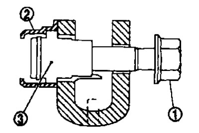
a. Remove the mounting bolt (1).
b. Remove the press-fitted cam nut holder (2) from the intermediate shaft fork.
c. Unscrew the cam nut (3) from the intermediate shaft fork.
11. Remove the cover from the steering column.
Installation
Installation is carried out in the reverse order of removal, taking into account the following:
Attention:
- When removing, do not allow the steering column assembly to be struck in the axial direction.
- Before removing the intermediate shaft, apply alignment marks to the intermediate shaft and steering column assembly.
- Do not turn the steering wheel when the vehicle is not stopped, as the electric motor and EPS control unit may overheat.
- Be careful when removing the steering column assembly from the vehicle as it is heavy.
- Do not expose the steering column assembly to magnetism.
- The steering column cannot be disassembled.
- When installing the steering column assembly, observe the following:
Caution: Do not reuse the cam nut and mounting bolt.
1. Make sure all components have been removed from the cam nut holder.
2. Attach the fork to the worm shaft so that there is no gap between them.
3. Insert the cam nut completely into place.
4. While holding the cam nut with your hand, insert the bolt and tighten to the specified torque. Keep the nut level while screwing the bolt in.
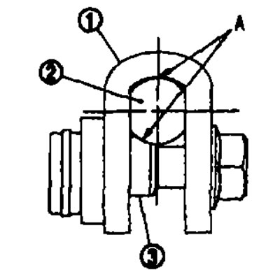
5. After installing the intermediate shaft, make sure that there is no gap (A) between the fork (1), worm shaft (2) and cam nut (3).
Attention:
- Do not reuse the cam nut holder.
- When tightening the mounting bolt, do not clamp the cam nut with the tool.
- Perform steering angle sensor neutral position adjustment.
Check after removal
- Check all components of the steering column assembly for damage or other abnormalities. Replace if necessary.
- Measure the steering column turning torque using a preload measuring device (special tool: ST3127S000). If the torque is different from the norm, replace the steering column assembly.
Standard.
Rotation moment. See the section "Technical data and specifications" below.
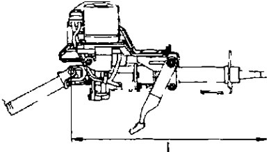
- If the vehicle has been involved in a minor collision accident, measure the length "L" as shown in the figure. If the length is different from the standard, replace the steering column assembly.
Standard.
Steering column length "L": See "Technical data and specifications" section below.
Post-installation check
Check all components of the steering column assembly for damage or other abnormalities. Replace if necessary.
Check the play, neutral position, steering wheel turning moment and front wheel turning angles. See above.
Check the operating range "L1", "L2" tilt and height adjustment mechanism of the steering column, as shown in the figure.
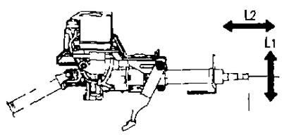
Standard:
- Working range of tilt adjustment "L1": See below section "Technical data and specifications".
- Working range of height adjustment "L2": See below section "Technical data and specifications".