


Table of contents: Removal ↓ Installation ↓ Disassembly ↓ Cleaning and checking the condition…↓ Assembly ↓
Removal
1. Disconnect the negative cable from the battery.
2. Mark the position of the steering shaft in relation to the flexible coupling with quick-drying paint. Loosen the upper coupling clamp bolt.
3. Remove the steering wheel.
4. On models with adjustable speaker tilt, lower the speaker to the lowest position.
5. Loosen the screws securing the column covers. Set the covers aside, removing them from the combined steering column switch and ignition switch.
Note: On models with a standard column, you will need to loosen the bolts that secure the top of the column to the instrument panel, then lower the column slightly to remove the top cover.
6. Disconnect the wiring from the ignition switch and the combination steering column switch and ignition switch (from the back of them).
7. Loosen the lower nuts securing the hole cover, which secure the lower part of the column to the engine compartment bulkhead.
8. Remove the steering column from the vehicle.
Installation
Installation is carried out in reverse order.
(See the source on the portal: Nissanbook.ru)
1. Align the steering shaft position marks made during dismantling with the flexible coupling and ensure that the coupling clamping bolt fits into the corresponding groove on the steering shaft. Tighten the clamping bolt - at this stage only by hand.
2. Install the upper bracket/tilt bracket bolts and screw on the hole cover nuts. Make sure that the steering column is installed without internal stress. Tighten the nuts to 9-14 Nm and the bracket bolts to 13-18 Nm.
3. Tighten the flexible coupling clamp bolt with a force of 39÷49 Nm.
4. Jack up the front of the vehicle and make sure that the steering wheel rotates freely from lock to lock in both directions without jerking or jamming.
Disassembly
1. Remove the steering column.
2. Loosen the screws of the mounting clamp, press down and turn the combination steering column switch. Remove the switch from the steering column.
3. Remove the plastic bandage, loosen the hole cover bracket mounting bolts, remove the washers and remove the hole cover bracket from the steering column.
4. Using special pliers, remove the retaining ring and washers from the top of the steering shaft. Remove the shaft from the column.
5. On models with adjustable column tilt (see accompanying illustration) loosen the tilt bracket bolt and special nut. Remove the tilt bracket from the column. Store the bracket components in the order they were removed.
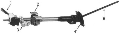
1 - combined steering column switch; 2 - column tilt bracket; 3 - ignition switch; 4 - hole cover; 5 - steering shaft
6. If necessary, remove the ignition switch (see accompanying illustration), using a center punch and hammer to drive in the shear-type fastening bolts.
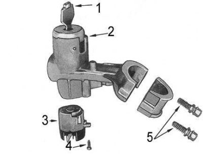
1 - ignition key; 2 - lock cylinder assembly; 3 - ignition switch; 4 - screw; 5 - shear bolts
Cleaning and checking the condition of components
1. Use solvent to remove traces of grease from metal components.
Warning! Do not wash the ignition switch and combined steering column switch assemblies, as well as any sealed bearings, in solvent - this may result in irreversible failure of the listed components.
2. Check the steering shaft for signs of wear, deformation and other damage. Pay particular attention to the condition of the universal joint (cardan) hinges and splined sections.
3. Check the condition of the retaining rings and spring clips. Replace any worn, damaged or stretched components.
4. Check the freedom of rotation of the lower bearing.
5. On a tilt type column, check the tilt adjustment mechanism components for signs of wear or damage.
6. Check the cover plate for signs of wear, deformation or other damage.
7. Replace all identified defective components.
Assembly
Steering Column Components
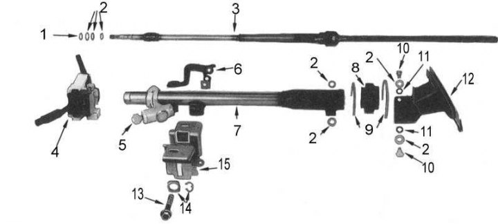
1 - retaining ring; 2 - washers; 3 - steering shaft; 4 - combined steering column switch; 5 - ignition switch; 6 - handle; 7 - column; 8 - protective cover; 9 - bandages; 10 - bolt; 11 - sealing ring; 12 - hole cover; 13 - special bolt; 14 - clamps; 15 - tilt bracket
Assembly is carried out in the reverse order of disassembly.
1. Before assembly, lubricate the upper and lower steering shaft bearings and all moving components of the tilt column adjustment mechanism with multi-purpose grease (if such is provided).
2. Make sure that the upper steering shaft retaining ring, located under the upper bearing, is turned with the rounded side towards the bearing.
3. When installing the hole cover bracket, ensure that the washers are positioned correctly. Tighten the axle bolts to 16÷21 Nm.
4. On models with a tilt type column, tighten the tilt bracket bolt so that the column moves smoothly when the tilt control lever is released, but remains stationary when the lever is locked.
5. Install the speaker on the car.