Note. The following special tools are required to complete the procedures below: a bipod puller and a 41mm socket or ring wrench (to remove the mechanism); interchangeable head type TORX E10 (to disassemble the mechanism); sensitive torque wrench and adapter for preload adjustment (for assembly).
Models of the early years of production (until 1992)
Adjustment
Note. No attempt should be made to adjust the steering gear without using a sensitive torque wrench - the result may be reduced vehicle controllability and shortened life of the steering gear components.
Removing
1. Set the front wheels and steering wheel straight ahead.
2. Use quick-dry paint to mark the position of the flexible coupling in relation to the steering gear worm shaft. Turn out a coupling bolt.
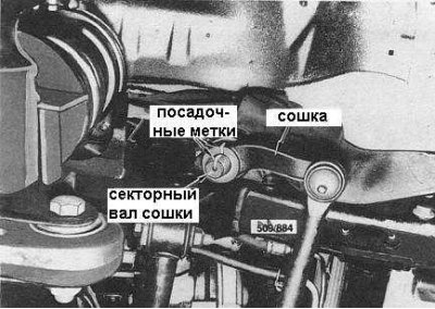
3. Give a nut of fastening of a bipod of the steering mechanism to a sector shaft, remove a washer. Mark the position of the steering arm in relation to the sector shaft (see accompanying illustration). Using a special puller, remove the bipod from the sector shaft.
4. Give hollow bolts of fastening to assembly of the steering mechanism of hydraulic lines. Place a drain pan under the lines to collect the escaping fluid.
5. Give nuts and bolts of fastening of the steering mechanism to the chassis. Remove the steering gear assembly from the vehicle.
Installation
Installation is in the reverse order.
1. Follow the alignment of all landing marks applied during dismantling.
2. Establish nuts and bolts of fastening of assembly of the steering mechanism. Tighten fasteners with a force of 84÷96 Nm.
3. Replace the copper sealing washers in the in-line connectors and securely tighten the banjo bolts.
4. Tighten the nut for fastening the bipod of the steering mechanism with a force of 235÷265 Nm.
5. Add fresh fluid to the reservoir and bleed the hydraulic system.
Disassembly
1. Remove the steering gear assembly from the vehicle.
2. Bring the worm shaft into the middle (rectilinear) position, for which turn it 2.14 turns (two full turns, plus another 50°). Back from the stop.
3. Loosen the sector shaft cover fastening bolts and use a soft-faced hammer to knock out the shaft from the steering gear housing by approximately 20 mm, then remove it by hand.
Note. After removing the sector shaft, do not allow the booster piston or worm shaft to move.
4. Carefully prying off, remove the boot from the end of the steering gear housing from the bipod side. Throw away the duster.
5. Remove the circlip and remove the large spacer by carefully prying it out with a suitable lever.
6. Carefully remove the oil seal from the steering gear housing - do not scratch the sealing surface of the housing with the lever.
7. Using a TORX E10 key, release the rear cover mounting bolts.
8. Carefully remove the back cover along with the booster piston and worm shaft from the steering gear housing. Take care not to move the components to prevent the circulation balls from falling out.
Note. Car manufacturers insist that if the gap between the piston and the rear cover exceeds 35 mm, the piston assembly with the worm shaft should be replaced.
9. Check the condition of the roller bearings, worm shaft bearings, sector shaft, and worm shaft/amplifier assembly. Replace excessively worn or damaged components.
Steering components
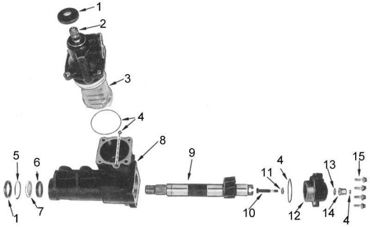
1 - anther; 2 - worm shaft; 3 - amplifying piston; 4 - sealing rings; 5 - retaining ring; 6 - stuffing box; 7 - remote bushing; 8 - crankcase; 9 - sector shaft bipod; 10 - adjusting screw; 11 - adjusting washer; 12 - cover; 13 - washer; 14 - locknut; 15 - bolts
Assembly
Assembly is carried out in the reverse order of dismantling.
Note. O-rings, spacers, oil seals, circlips and washers must be replaced every time the steering gear is dismantled. This means that in order to assemble the mechanism, you should purchase a special repair kit containing all the necessary replacement components.
1. Lubricate all components with hydraulic fluid before assembly.
2. Lubricate a new rear cover oil seal with a suitable sealant and install and seat it in the steering gear housing with a piece of pipe resting on the outer perimeter of the oil seal. Make sure that the stuffing box is turned by the main jaws to the booster piston.
3. Install new o-rings and Teflon rings in the back cover. Lubricate the rings with petroleum jelly for temporary fixation.
4. Install the worm shaft, booster piston and rear cover into the steering gear housing. Be careful not to damage the Teflon ring on the piston end. Make sure all o-rings are in place.
5. Screw in the bolts securing the rear cover and tighten them diagonally in two or three stages with a final torque of 26 ÷ 32 Nm.
Note. The booster piston must be in its normal operating position and not be skewed.
6. Lubricate the new sector shaft oil seal on the outside around the perimeter with a suitable sealant, then seat it perpendicularly into the steering gear housing using a piece of pipe that should rest against the outer edge of the oil seal. Lightly lubricate the gland bends with petroleum jelly.
7. Install the large spacer bushing in the steering gear case and secure it with the circlip. Make sure the retaining ring is turned with a rounded edge towards the stuffing box.
Note. On some models, the rounded side of the seal is marked with an R identification mark.
8. Install a new anther in the crankcase of the steering mechanism, planting it with a piece of pipe resting against the outer edge of the anther. Lightly grease the boot lips with petroleum jelly.
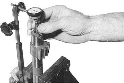
9. Check the axial play of the sector shaft (see accompanying illustration), make adjustments if necessary:
- Clamp the sector shaft in a vise with soft jaws.
- Install the dial meter with the plunger to the end of the adjusting screw, then move the screw up and down for the entire length of its stroke and read the readings of the device. The nominal value of the axial play of the sector shaft is 0.01÷1.05 mm.
- If necessary, remove the adjusting screw from the shaft and install new adjusting washers of the required thickness. If you cannot achieve the nominal value of the axial play, replace the adjusting screw.
10. Install a new O-ring on the sector shaft cover. Lightly lubricate it with petroleum jelly. Using a small, sharp tool, remove the O-ring from the sector shaft adjusting screw locknut. Using a blunt tool, install a new O-ring after lubricating it with petroleum jelly.
11. Rotate the worm shaft to drive the booster piston to a straight position.
12. Wrap the splines of the sector shaft with tape.
13. Rotate the booster piston with the teeth upwards towards the top of the steering box at an angle of approximately 10°÷15°to ensure free installation of the sector shaft.
14. Install the sector shaft in the crankcase. Make sure the booster piston stays in the center position.
15. Screw in the bolts securing the sector shaft cover and tighten them diagonally in two or three stages with a final torque of 26÷32 Nm.
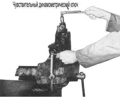
16. Clamp the steering mechanism assembly in a vise at approximately the normal mounting angle and check its turning force.
- Rotate the worm shaft from lock to lock several times to shrink the steering gear components
Note. If jerks and bite points occur during the rotation of the worm shaft, adjust the position of the adjusting screw accordingly.
- Using a sensitive torque wrench with a suitable nozzle, measure the turning force of the worm shaft. The measurement is made from a straight shaft position. The nominal value is 0.59÷1.34 Nm.
Note. If a suitable nozzle is not available, you can wrap the end of the shaft with tape and use a tight-fitting polygonal socket.
- Repeat the test procedure after rotating the worm shaft 360°from the center position. This time the nominal value is 0.2÷0.4 Nm less than the above.
- If the turning force of the worm shaft falls within the specified values, tighten the lock nut with a force of 34÷40 Nm, while holding the adjusting screw motionless.
- If the shaft turning force is out of range, correct the position of the adjusting screw accordingly. If it is not possible to achieve a hit of the force in the norm, the steering mechanism assembly must be replaced.
17. Establish assembly of the steering mechanism on the car.
Models of later years of release (since 1992)
The above procedure for performing the procedures remains valid, subject to the following remarks:
- The sector shaft boot, locking ring and spacer sleeve have been removed from the steering gear assembly. The O-ring of the adjusting screw locknut with washer has also been removed.
- An additional flexible seal is installed between the outer seal of the sector shaft and the roller bearing in the crankcase. This oil seal must be seated with the grooved side facing the bearing.
- A flexible gland is also installed on the sector shaft cover. The grooved side must face the bearing.