


Table of contents: Removal ↓ Installation ↓ Disassembly ↓ Cleaning and checking the condition…↓ Assembly ↓
Utility and Mini-truck models (Cab Chassis).
Note: To perform the work described below, you will need the following special tools: a sensitive torque wrench (for measuring the initial moment of rotation of the pendulum lever); special steering knuckle puller (to remove the pendulum lever).
Removal
1. Jack up the front of the car and place it on supports.
2. Remove the cotter pins, then loosen the crown nuts securing the pendulum arm assembly to the longitudinal and transverse steering rods.
3. If a puller is not available, release the ball joints of the swingarm assembly using an alternative method using two hammers.
4. Loosen the bolts securing the tie rod end assembly to the chassis and remove the assembly from the vehicle.
Installation
Installation is carried out in reverse order.
1. Tighten the assembly mounting bolts to 45÷55 Nm.
2. The nominal tightening force of crown nuts is 88÷113 Nm.
3. Cotter pins must be replaced without fail.
4. Finally, using a grease gun, lubricate the pendulum arm assembly with the required grade of grease.
Disassembly
1. Remove the tie rod end swing arm assembly from the vehicle.
2. Clamp the assembly firmly in a vice with soft jaws. Remove the cotter pin and loosen the mounting nut (the assembly components are shown in the accompanying illustration). Using a steering knuckle puller, remove the pendulum arm from its axle.
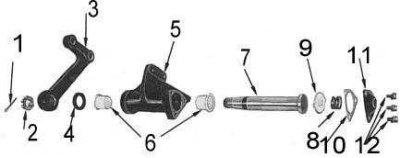
1 - cotter pin; 2 - nut; 3 - pendulum lever; 4 - oil seal; 5 - casing; 6 - bushings; 7 - axis; 8 - spring; 9 - spring plate; 10 - gasket; 11 - lid; 12 - bolts
3. Loosen the bolts securing the pendulum arm cover to the casing.
4. Remove the spring with its plate, discard the gasket.
5. Remove the axle from the housing and remove the upper bushing.
6. Using a suitable punch and hammer, carefully tap the seal out of the lower end of the housing, then remove the lower bushing.
Cleaning and checking the condition of components
1. Wash all assembly components in a suitable solvent, then dry them thoroughly.
2. Inspect the assembly housing for cracks and other damage.
3. Check the condition of the axle, casing and bushings. If signs of wear or damage are found, replace the defective components.
4. Check the condition (degree of wear and weakening of the compression force) springs.
5. Inspect the lever for cracks and other damage.
Assembly
Assembly is carried out in the reverse order of disassembly.
1. Install the bushings into the pendulum arm housing.
2. Lubricate the new seal on the outside with a suitable sealant, then seat it using a mandrel from below in the casing. Lubricate the seal lips with a universal grease.
3. Lubricate the contact surfaces of the housing bushings and the axle with general-purpose grease, then insert the axle into the housing
4. Install the plate and spring. Make sure that the spring plate tabs are correctly positioned in the casing.
5. Install the swingarm housing cover with a new gasket, tighten the mounting bolts securely.
6. Place the lever on the axle, tighten the mounting nut securely and secure it with a cotter pin.
7. Measure the initial torque of the pendulum arm:
- Grasp the lever and move it back and forth in a range of approximately 90° to distribute the grease.
- Place a replacement socket head onto the lever axle nut.
- Connect a sensitive torque wrench to the head and, applying force to the wrench collar, read the torque value at the moment the lever starts moving. The nominal value is 4.9 Nm.
- If the measurement result does not correspond to the required value, the lever must be disassembled and the cause of the jamming eliminated.