


Table of contents: Hardtop Models and a station wagon…↓ Steering link rod ↓ Utility and Mini-truck models ↓
Note: A sensitive torque wrench is required to measure the ball joint rotation force.
Hardtop Models and a station wagon (Station Wagon)
Attention! Transverse steering rod and steering damper
Relative position and fastening details of the transverse steering rod and steering damper
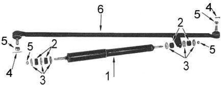
1 - steering damper; 2 - rubber bushings; 3 - washers; 4 - cotter pin; 5 - nut; 6 - transverse thrust
Removal
1. Jack up the front of the vehicle and support it on stands. It may be necessary to remove the left front wheel to gain access to the left front ball joint.
2. On early model years, loosen the nut securing the steering damper to the transverse steering rod and remove the washer. Loosen the nut and bolt securing the damper to the transverse reaction rod and remove the damper from the car.
Note: On some models, the steering damper is attached to the chassis frame instead of the transverse reaction rod. In this case, you must provide the appropriate fasteners instead.
3. On later models, loosen the nuts on both ends of the steering damper while holding the damper rod still with a wrench. Remove the washers and rubber bushings, then lift the steering damper out from under the car.
4. Remove the cotter pins from the castle nuts at both ends of the tie rod. Unscrew the nuts.
5. If a puller is available, use it to release the tie rod ball joints from the steering knuckle and steering arm.
6. If a puller is not available, remove the ball joint pins by pressing the striker of one hammer against the corresponding seat ear and striking the back of the ear with the second hammer.
7. Remove the tie rod from the vehicle. Check the rod for cracks and signs of deformation, and replace it if necessary.
8. Check the ball joints for axial play by grasping the joint with one hand and trying to move the ball pin from side to side with the other. If there is play, replace the tie rod.
9. Check the turning force of the ball joints by tightening the nuts, clamping the rod in a vice and rotating the ball pin using a sensitive torque wrench (see accompanying illustration). The nominal turning force of the ball joint is between 1.0 and 4.9 Nm. Replace the rod if necessary.
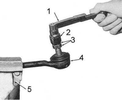
1 - torque wrench; 2 - replaceable socket head; 3 - two nuts; 4 - ball joint; 5 - vice
10. Check the condition of the ball joint boots. Replace any defective ones.
11. Check the condition of all threads, replace defective components.
12. Grasp both ends of the steering damper and squeeze it hard several times until the end of its stroke. If there is jerking or sticking points, the damper should be replaced.
13. Inspect the damper body for dents, other damage, and signs of fluid leakage. Replace if necessary.
14. Check the condition of the rubber bushings of the damper supports. Replace defective bushings.
Installation
Installation is carried out in reverse order.
1. Tighten the castle nuts to 46÷54 Nm.
2. Cotter pins must be replaced without fail.
3. Lubricate all joints with the recommended type of grease (see size and adjustment tables at the end of the Guide).
Steering link rod
Removal
1. Jack up the front of the vehicle and support it on stands. You may need to remove the wheels to gain access to the hinges.
2. Remove the cotter pins from the castle nuts at both ends of the connecting rod. Release the nuts.
3. If you have a puller, use it to release the tie rod end ball joints from the steering knuckles.
4. If a puller is not available, use the alternative method described for the tie rod joints.
5. Remove the tie rod from the vehicle.
6. Check the rod for cracks and signs of deformation. Replace if necessary.
7. Check the ball joints of the tips for axial play by grasping the joint with one hand and trying to swing the ball pin from side to side with the other. If there is play, replace the connecting rod.
8. Check the ball joint turning force by tightening the nuts, clamping the rod in a vice and turning the ball pin with a sensitive torque wrench. The nominal turning force of the ball joint is between 1.0 and 4.9 Nm. If necessary, replace the corresponding rod end.
9. Check the condition of the ball joint boots. Replace any that are defective.
10. Check the condition of all threads, replace defective components.
Installation
Installation is carried out in reverse order.
1. Measure the length of the rod between the centers of the ball joints of the tips. The nominal value is about 1,270 mm. Make adjustments if necessary. The tips should protrude from the rod by approximately the same number of thread turns (the details of the tie rod end are shown in the accompanying illustration).
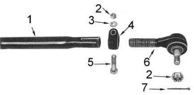
1 - connecting rod; 2 - nut; 3 - washer; 4 - clamp; 5 - bolt; 6 - tip; 7 - cotter pin
2. Tighten the castle nuts to 46÷54 Nm.
3. Cotter pins must be replaced without fail.
4. Tighten the locking clamps of the steering rod ends with a force of 25÷28 Nm.
5. Lubricate all joints with the recommended type of grease (see size and adjustment tables at the end of the Guide).
6. Check the front wheel alignment of the vehicle and make adjustments if necessary.
Utility and Mini-truck models
(Cab Chassis)
Steering components for Utility (Van) and Mini-truck models (size A is 1236 mm)

1 - nut; 2 - steering damper; 3 - washers; 4 - transverse steering rod; 5 - cotter pin; 6 - assembly of the pendulum arm of the transverse steering rod; 7 - longitudinal steering rod; 8 - connecting steering rod
Removal
Longitudinal steering rod
1. Jack up the front of the car and place it on supports.
2. Remove the cotter pins from the castle nuts at both ends of the tie rod. Release the nuts.
3. If you have a puller, use it to disconnect the ball joints of the longitudinal rod from the connecting rod and assemble the pendulum arm of the transverse rod.
4. If a puller is not available, use the alternative method described for Hardtop and Estate tie rod joints.
5. Remove the longitudinal rod from the vehicle.
Transverse steering rod
1. Jack up the front of the car and place it on supports.
2. Remove the cotter pins from the castle nuts at both ends of the tie rod. Release the nuts.
3. Loosen the steering damper mounting nut, remove the washer and lift the damper up, removing it from the stud on the crossbar.
4. If you have a puller, use it to separate the tie rod ball joint pins from the idler arm and steering knuckle assembly.
5. If a puller is not available, use the alternative method described for Hardtop and Estate tie rod joints.
6. Remove the tie rod from the vehicle.
7. Check the rod for cracks and signs of deformation. Replace if necessary.
Steering link rod
1. Jack up the front of the vehicle and support it on stands. You may need to remove the wheels to gain access to the hinges.
2. Remove the cotter pins from the castle nuts at both ends of the tie rod and from the longitudinal rod. Release the nuts.
3. If you have a puller, use it to separate the tie rod end ball joints from the steering knuckle and tie rod.
4. If a puller is not available, use the alternative method described for Hardtop and Estate tie rod joints.
5. Remove the tie rod from the vehicle.
6. If necessary, loosen the lock plate bolts (see accompanying illustration) and the bolts of the clamps securing the connecting rod ends. Remove the ends. Count and record the number of turns required to unscrew each end.
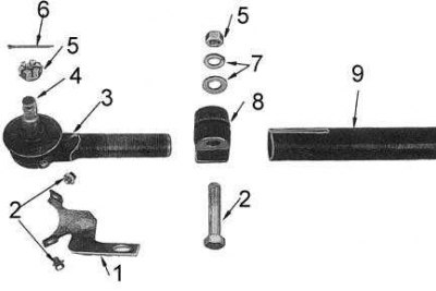
1 - locking plate; 2 - bolts; 3 - traction rod end; 4 - ball joint pin; 5 - nut; 6 - cotter pin; 7 - washers; 8 - clamp; 9 - connecting rod
Checking the status of components
1. Check all steering components for signs of wear or damage.
2. Check the tie rod ball joints for axial play by grasping the joint with one hand and trying to move the ball pin from side to side with the other. If there is play, replace the joint.
3. Check the turning force of the ball joints of the rods by tightening the nuts, clamping the rod in a vice and turning the ball pin using a sensitive torque wrench. The nominal turning force of the ball joint is between 1.0 and 4.9 Nm. Replace defective joints.
4. Check the condition of the ball joint boots. Replace any defective ones.
5. Check the condition of all threads, replace defective components.
Installation
Installation is carried out in reverse order.
1. If removed, install the ends on the connecting steering rod, screwing them in the same number of turns.
Note: The overall length of the tie rod assembly (1,236 mm) should be measured between the centers of the ball studs of the ends.
2. Install the locking plates onto the tie rod ends.
3. Tighten the castle nuts and bolts of the tie rod end clamps to the required torque.
4. Cotter pins must be replaced without fail.
5. Lubricate all joints with the recommended type of grease (see size and adjustment tables at the end of the Guide).
6. Check the front wheel alignment of the vehicle and make adjustments if necessary.