


Table of contents: Seal and axle shafts ↓ Removal and installation ↓ Removal and installation ↓ Post-installation check ↓ Breather hose ↓ Removal and installation ↓
Seal and axle shafts
Removal and installation
Removal
1. Remove the front drive shafts. See chapter "Front axle and suspension".
2. Remove the differential seals (1) using a suitable tool.
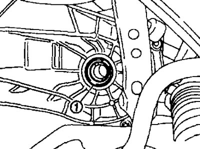
Caution: Do not damage the gearbox and clutch housings.
Installation
Installation is carried out in the reverse order of removal, taking into account the following:
- Press the seals (1) into the clutch and gearbox housing using a punch (A) (special tool: KV3B100300).
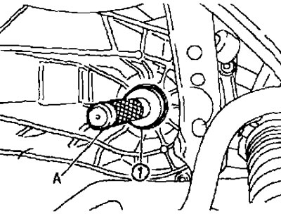
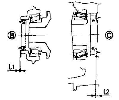
B. From the gearbox side; C. From the clutch housing side
Size "L1": 1.2-1.8 mm.
Size "L2": 2.7-3.3 mm.
Attention:
- Do not reuse the seal.
- Do not tilt the seal when pressing it in.
- Do not damage the gearbox and clutch housings.
- After installation, check the oil level and check for leaks. See above.
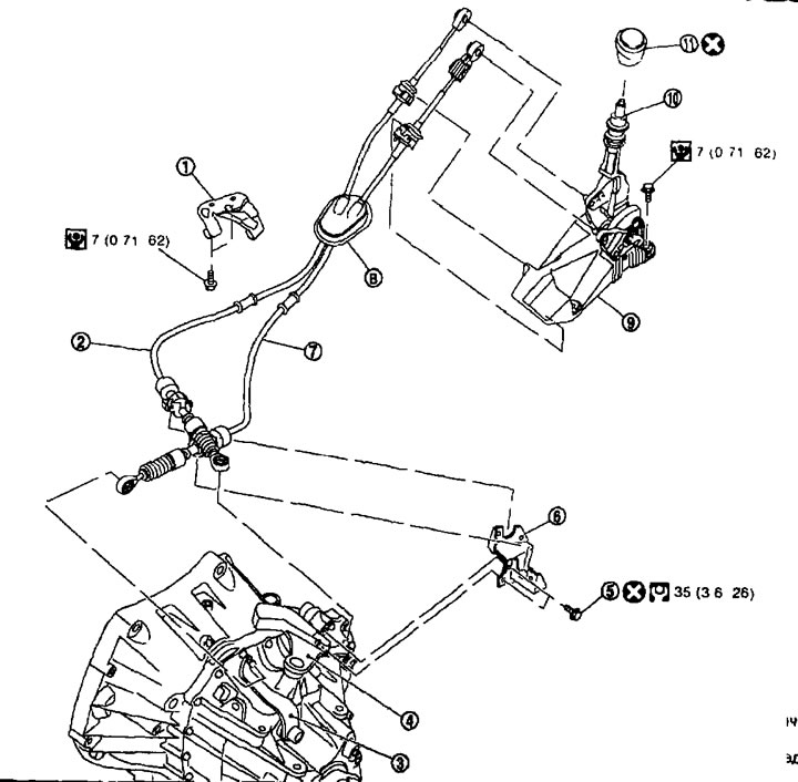
Gearbox control lever mechanism. 1. Bracket; 2. Gear shift cable; 3. Gear selector lever; 4. Shift lever; 5. Self-tapping bolt; 6. Cable mounting bracket; 7. Gear selection cable; 8. Rubber bushing; 9. Gear shift mechanism assembly; 10. Gear shift lever; 11. Gear shift lever handle.
Removal and installation
Removal
1. Remove the air cleaner housing and the air duct (inlet) or ducts. See Chapter "Mechanical part of the engine".
2. Remove the battery.
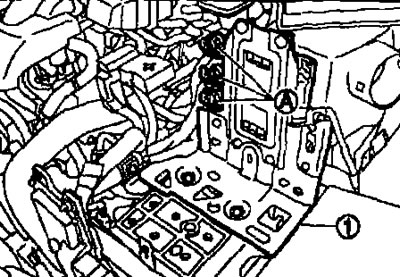
3. Disconnect the connectors (A) and then remove the bracket (1).
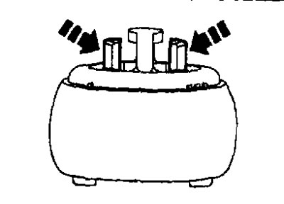
4. While squeezing the gear selector cable lock in the direction of the arrow as shown in the figure, disconnect the gear selector cable from the gear selector lever.
5. While squeezing the shift cable clamps in the direction of the arrow as shown in the figure, disconnect the shift cable from the shift lever.
6. Pull the gear selector cable locks in the direction of the arrow as shown in the figure to remove the gear selector cable from the mounting bracket.
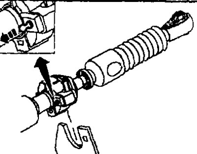
7. Pull the shift cable locks in the direction of the arrow as shown in the illustration to remove the shift cable from the mounting bracket.
8. Remove the gear shift knob.
Note: Pull the gear shift knob and remove it.
9. Remove the console trim assembly and center console assembly. Refer to Chapter "Interior and exterior body equipment".
10. Move the gear shift lever to neutral position.
11. While squeezing the gear selector cable clamps in the direction of the arrow as shown in the illustration, disconnect the gear selector cable from the gear shift mechanism assembly.
12. While squeezing the shift cable clamps in the direction of the arrow as shown in the illustration, disconnect the shift cable from the shift mechanism assembly.
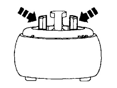
13. Pull the gear selector cable locks in the direction of the arrow as shown in the illustration to remove the gear selector cable from the gear shift assembly.
14. Pull the shift cable locks in the direction of the arrow as shown in the illustration to remove the shift cable from the shift mechanism assembly.
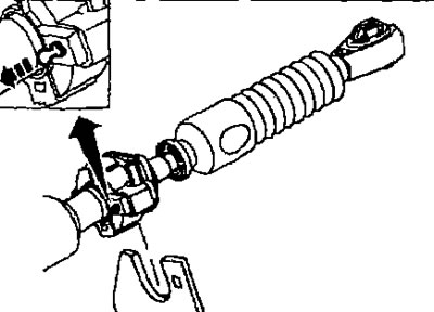
15. Remove the gear shift mechanism assembly.
16. Remove the heat shield.
17. Remove the bracket.
18. Remove the rubber bushing and remove the gear shift cable and gear selector cable from the vehicle.
Installation
Installation is carried out in the reverse order of removal, taking into account the following:
- Move the gear shift lever to neutral position.
- Securely connect each cable to the shift lever and shift lever and install each cable securely to the mounting bracket.
- Securely connect each cable to the shift assembly.
- Make sure the rubber bushing tabs are in contact with the floor surface.
- Place the handle on the gear shift lever observing the installation direction.
Caution: Do not use the gearshift lever knob again.
- Pre-cutting of the thread for the self-tapping bolt in the new clutch housing is not performed. The thread is cut when screwing the self-tapping bolt into the clutch housing.
Caution: Do not reuse the self-tapping bolt.
- Connect the gear selector cable (from the gearshift assembly side) as follows:
1. Pull the shift cable locks in the direction of the arrow as shown in the figure to connect the shift cable to the shift mechanism assembly.
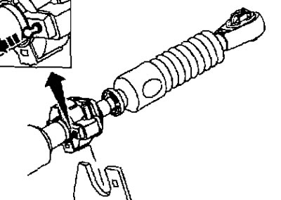
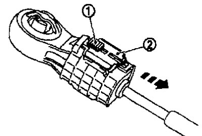
2. Slide the lock (1) of the gear selector cable in the direction of the arrow as shown in the figure and pull the stopper (2) of the gear selector cable.
3. Place the gear selector cable end onto the gear shift assembly pin.
4. Insert the lever lock pin (1) or rod (diameter 3 mm) into the gear shift mechanism assembly.
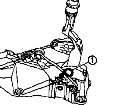
Caution: Perform fine adjustment of the gear selection cable without using the locking pin on the lever or rod (diameter 3 mm) it is forbidden.
Note: The lever lock pin is not included in the gear shift mechanism kit. Therefore, if the mechanism is not being replaced, stock up on a rod (diameter 3 mm).
5. Make sure that the gearshift lever does not move in the direction of gear selection. If it does, repeat step 3.
6. Move the gear shift lever to the 4th gear position.
7. After pressing the stopper (1) of the gear selector cable, move the lock (2) of the gear selector cable in the direction of the arrow.
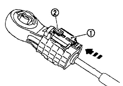
8. Insert the lever lock pin or rod (diameter 3 mm) from the gear shift mechanism assembly.
9. Move the gearshift lever to all positions and make sure that it does not stick. Otherwise, repeat step 3.
Post-installation check
- Make sure that when you shift the lever towards 1st/2nd gear and towards 5th/6th gear, the shift lever smoothly returns to the neutral position.
- Make sure that the gearshift lever does not stick and is locked in each position when changing gears.
Breather hose
Removal and installation
Removal
When removing, refer to the drawing on the next page.
Caution: When removing the breather hose, hold the two-way coupling securely.
Installation
- When installing, refer to the drawing on the next page.
- When connecting the breather hose to the two-way coupling, turn the paint mark toward the front of the vehicle.
- When connecting the breather hose to the two-way coupling, push it in until it rests against the transmission housing.
- When connecting the breather hose to the air cleaner housing, make sure the clamp is fully inserted.
Caution: Make sure that there are no pinched or narrowed areas on the breather hose that may have formed when it was bent or folded during installation.
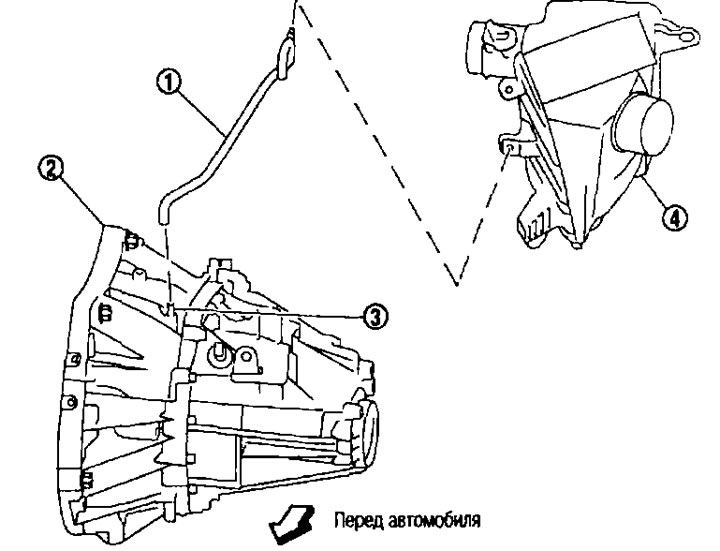
Breather hose. Removal and installation 1. Breather hose; 2. Gearbox assembly; 3. Two-way coupling; 4. Air cleaner housing.
The publication is reprinted from this resource NISSANBOOK.RU