


Table of contents: Door latch ↓ Door strike plate ↓ External handle - front door ↓ External handle - rear door ↓ Inner handle ↓ Interior Lock Button - Front Door ↓ Interior Lock Button - Rear Door ↓
Door latch
1. Open the door, close the window completely, then remove the door interior trim panel (see Chapter 33 of this Section).
2. Remove the polyethylene protective seal to expose the valve.
3. Disconnect the rods connecting the outer valve from the valve (only at the front doors) and internal handles, internal lock button, lock cylinder (only at the front doors) and, if fitted, the central locking switch or actuator. Each link is secured by a spring clip which must be removed before the link can be disconnected.
4. Remove the bolt mounting screws and remove the bolt (see photo).
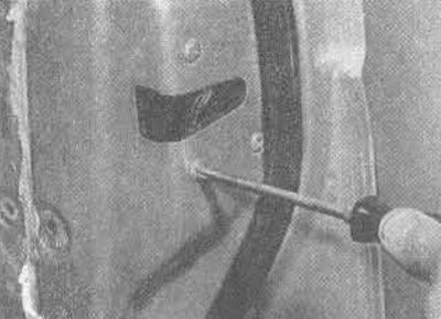
26.4A. Remove the mounting screws...
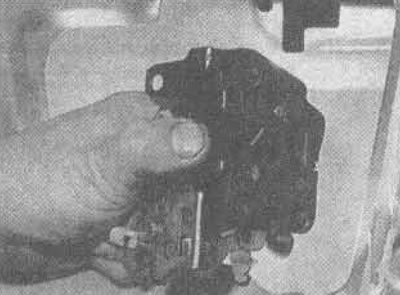
26.4B... remove the door latch assembly
(The publication is reprinted from this resource: «nissanbook.ru»)
5. Assembly is carried out in the reverse order. Before assembly, lubricate the tips and parts of the valve. Adjust the rods (if necessary) as described below.
Door strike plate
6. Open the door and mark the position of the strike plate.
7. Remove the mounting screws and remove the strike plate, noting the gasket behind it.
8. When assembling, adjust the position of the strike plate (if necessary) as described in Chapter 25, Section 7, tighten the screws securely.
External handle - front door
9. Open the door and make sure the window is completely closed, then remove the door interior trim panel (see Chapter 33 of this Section).
10. Pull out the edge of the polyethylene protective seal and remove the clip to detach the handle rod (see photo).
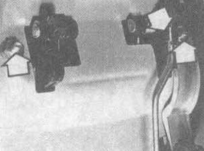
26.10. Outer door handle rod bracket and mounting nuts (marked with arrows)
11. Where installed, remove the keyhole light switch from the handle.
12. Remove the access plug to the handle mounting nut that is closest to the valve.
13. Unscrew the two handle mounting nuts, remove the lock cylinder and both gaskets, then remove the handle from the outside of the door.
14. Reassemble in reverse order. Apply a little grease to the tip and pivot points of the handle, then check its adjustment.
15. When the front outside door handle is adjusted correctly, it should have a play of 0.8 to 4.1 mm before it begins to lift the latch. The latch travel before fully opening should be 12.8 to 16.1 mm. Adjustment is made by turning the plastic fastening nut in the latch with the end of the handle rod (see photo). The adjustment is done correctly when the play between the nut and the valve lever is from 0.5 to 2.5 mm (see figure 11.16.)
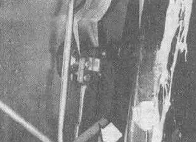
26.15 Adjusting nut of the outer door handle rod (shown by arrow)
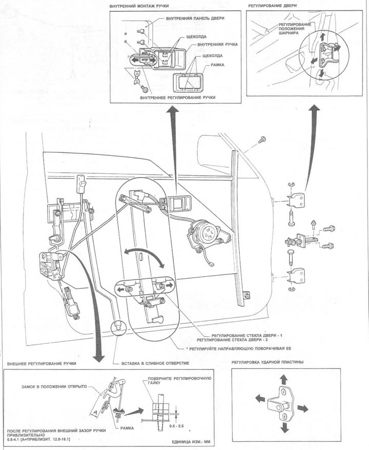
Figure 11.16. Front door details
External handle - rear door
16. Except that there is no connecting rod between the handle and the latch, and there is no backlight bulb, removal and installation is carried out as described in Points 9 through 14 above.
17. Adjustment of the rear door outer handle should be carried out as described in Item 15 above, but in fact it can be done by turning the latch adjuster (see figure 11.17.)
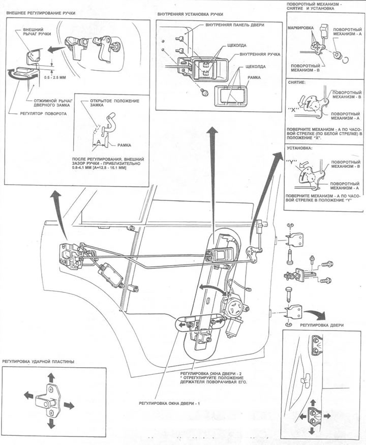
Figure 11.17. Rear door details
Inner handle
18. Open the door and make sure the window is completely closed, then remove the door interior trim panel (see Chapter 33 of this Section).
19. Remove the polyethylene seal. Pull out the bracket securing the handle tip to the valve and disconnect the rod.
20. Mark the position of the handle with a pencil, remove the two mounting screws and remove the handle (see figure 11.16 or 11.17), release the rod from the guide bracket (see photo).
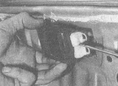
26.20. Removing the inner door handle
21. When assembling, connect the rod to the latch and press it into the guide bracket, then install the handle. Tighten the two screws and make the necessary adjustments until all excess play is eliminated. Tighten the screws completely (see photo).
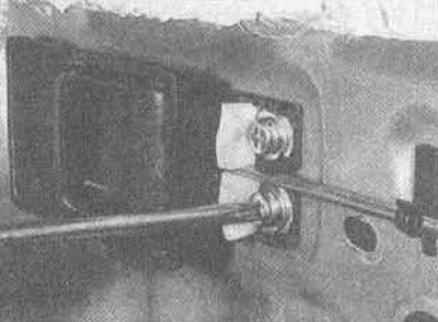
26.21. Adjust the position of the handle before tightening the screws
Interior Lock Button - Front Door
22. Open the door and make sure the window is completely closed, then remove the door interior trim panel (see Chapter 33 of this Section).
23. Remove the polyethylene seal and pull out the bracket that secures the pushbutton rod to the valve. Remove the pushbutton and rod (see photo).
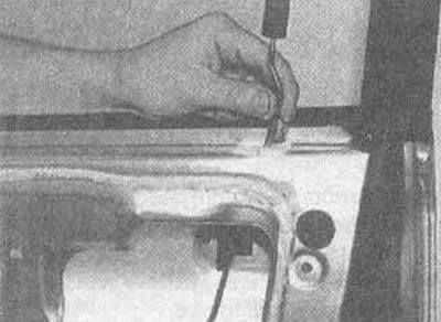
26.23. Removing the interior button and rod of the front door lock
24. Assembly is carried out in reverse order.
Interior Lock Button - Rear Door
25. Open the door and make sure the window is completely closed, then remove the door interior trim panel (see Chapter 33 of this Section).
26. Remove the polyethylene seal and pull out the bracket to disconnect the rotary mechanism rod from the valve.
27. Turn the black plastic rotary mechanism 'A' counterclockwise (to the 'X' position, Figure 11.17) and remove it from the door (see photo). Unfasten the button rod from the mechanism, pull its rod out of the guide bracket and remove them.
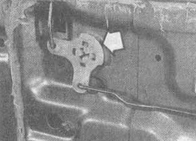
26.27. Turn the mechanism type 'A' (marked with an arrow), to take it out
28. Assembly is done in reverse order. Lubricate the tips and turn the mechanism - 'A' counterclockwise to place it on 'Y'.