


Cars with steel wheels
2. Remove the wheel cap, or center cap. Remove the black plastic cap (if any) from the end of the drive shaft, remove the shaft nut pin. Remove the locking ring and soft gasket. Loosen the shaft nut, but do not unscrew it completely.
3. Loosen the wheel nuts, lift
8. Open the hood, loosen the three nuts of the upper suspension strut mount by 1-2 turns.
9. Unscrew the three nuts from the bottom of the hub fastening element, remove the fastening plate, and sharply pull the hub fastening element out of the drive shaft grooves.
10. Unscrew the two nuts and bolts securing the hub element to the suspension strut, remove the hub fastening element.
11. Remove and replace the hub and bearings, if required, as described in Chapter 4 of this Section.
12. Remove and replace the lower control arm ball joint, if required, as described in Chapter 5 of this Section.
13. The brake disc shield can only be removed after the hub and bearings have been removed. Mark the shield's position relative to the fastener before removing.
Original publication on the portal (NISSANBOOK)
14. Do not tighten the steering gear lock bolt unless necessary. If the bolt or hub fastener has been replaced, tighten the bolt to the specified length (see Figure 10.42), tighten the lock nut, install the plastic cap and (where is available) pin. After lowering the car to the ground, check the maximum turning angles of the front wheels.
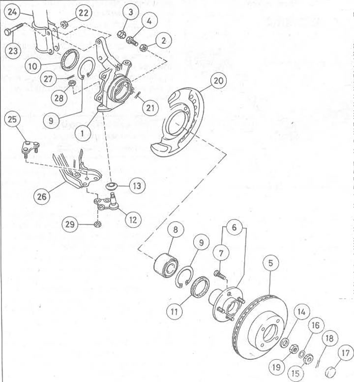
Figure 10.4. Front hub and bearings: 1. Hub fastening element; 2. Lock nut; 3. Plastic cap; 4. Steering column lock bolt; 5. Brake disc; 6. Hub; 7. Wheel stand; 8. Assembling the hub bearing; 9. Retaining ring; 10. Inner seal with plastic lubricant; 11. External seal with plastic lubricant; 12. Ball joint of the lower arm; 13. Dust-proof rubber cap of ball joint; 14. Metal gasket; 15. Locking ring; 16. Soft pad; 17. Black plastic cover, (if any); 18. Pin; 19. Drive shaft nut; 20. Brake disc shield; 21. Pin (if any); 22. Nut; 23. Clamp bolt; 24. Suspension strut; 25. Lower arm ball joint mounting plate; 26. Lower suspension arm; 27. Pin; 28. Ball joint lock nut; 29. Nut
15. When assembling, install the hub fastener to the suspension strut, insert the two bolts with the heads first, tighten the lock nuts to the tightening torque specified in the Specifications.
16. Insert (if it was removed) lower control arm ball joint to hub fastener, insert hub fastener assembly into drive shaft grooves, install ball joint fastener plate, tighten three nuts to torque specified in Specifications.
17. Tighten the upper suspension strut mounting nuts to the tightening torque specified in Specifications.
18. Install the outer tie rod ball joint to the hub retainer, tighten the lock nut to the torque specified in the Specifications and seat the new pin.
19. Install the brake disc on the hub, remove the spacer between the brake pads, install the brake caliper. Tighten the two bolts to the tightening torque specified in Specifications.
20. Install the metal spacer and drive shaft nut, then the wheel and lower the vehicle. Tighten the drive shaft nut to the torque specified in Specifications, install the soft gasket and locking ring.
21. On vehicles with steel wheels, seat the new pin, then install the wheel cover or center cap; don't forget to install the black plastic cover (if any).
22. On vehicles with alloy wheels, raise the vehicle and remove the wheel so that the new driveshaft nut retaining pin can be installed. Install the black plastic cover (if any). Install the wheel and center cap, lower the vehicle and tighten the wheel nuts to the torque specified in Specifications.
23. It may be necessary to adjust the wheel alignment and maximum steering angles.