


2. Clamp the hub fastener in a vice and use a hammer and a metal bar of a suitable diameter to knock the hub out of the fastener (Figure 10.5). Remove the brake disc shield from the hub mounting if necessary.
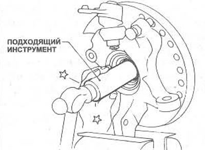
Figure 10.5. Removing the hub from the fastener
3. Using a suitable extractor (Figure 10.6), remove the inner ring from the hub, remove the seal with plastic lubricant.
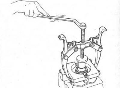
Figure 10.6. Using an extractor to remove the hub bearing ring
4. Remove the inner bearing ring.
5. Remove the retaining rings and knock the outer bearing ring out of the hub fastener.
6. Clean the bearing, hub and hub fastener. Check all components, replace if necessary.
7. If the wheel strut needs to be replaced, it must be pressed out of the hub flange. Note that the struts and hub are marked with an "N" or "R" symbol. Before replacing parts, check that the new part has the same designation as the old one being replaced.
8. When assembling, install the first snap ring into the inner groove of the hub fastener, then install the outer bearing ring into the hub fastener until it is against the snap ring. Install the second snap ring.
9. Lubricate the inner bearing races and install them into the outer bearing race. If using old bearings, check that each inner race is installed in its original position.
10. Lubricate the seal lips and tap the outer seal into the hub retainer.
11. Place the hub on the block and lower the fastener onto it. Using a hammer and socket on the inner bearing race, tap the fastener assembly onto the hub (figure 10.7).
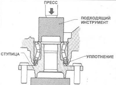
Figure 10.7. Installing the fastener on the hub and bearings
12. Check that the bearing is installed correctly, measure the torque, which should be within the specified range.
13. If a press is available, apply 49 kN of pressure to the bearing inner race. Quickly turn the hub fastener a few turns in each direction, then measure the torque with a spring balance attached to the pinch bolt hole at the top of the suspension strut (see figure 10.8); the resulting value must be within the specified range.
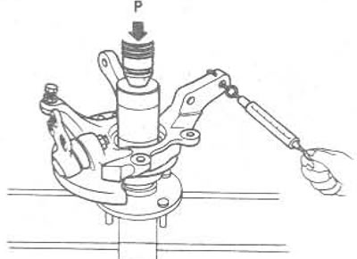
Figure 10.8. Checking the torque of the front hub bearing on the fastener
14. If a press is not available, temporarily fit the hub fastener assembly to the vehicle so that the drive shaft nut can be tightened to the torque specified in the Specification. Alternatively, the drive shaft can be removed and attached to the hub fastener clamped in a vice for testing. Rotate the hub quickly a few turns in each direction, then measure the torque with a spring balance attached to one of the wheel posts (see figure 10.9); the resulting value must be within the specified range.
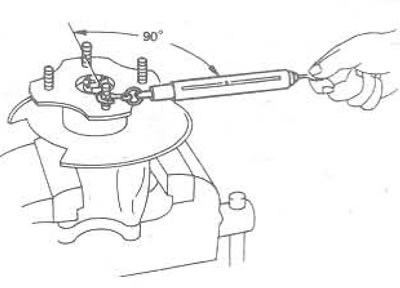
Figure 10.9. Checking the torque of the front hub bearing on the wheel stand
15. If the torque is incorrect, the bearings may be faulty or too tight.
16. Once the hub is properly seated on the bearings, lubricate the seal lips and hammer the inner seal into the hub retainer; the outer flange should protrude no more than 3.5 mm from the hub mounting element (see figure 10.10).
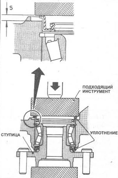
Figure 10.10. Installing the inner seal on the hub fastener The protrusion S should be no more than 3.5 mm
17. Install the hub retainer onto the vehicle.