


Table of contents: Differential bearing preload ↓ Output shaft bearing preload ↓ Input shaft lateral play ↓
Differential bearing preload
1. The required procedure is the same as described in Chapter 11, noting the following differences, along with different preload and torque:
- (a) Split tool number KV38106500
- (b) Thickness of required gaskets - measured value plus 0.40-0.46mm
- (c) Gaskets are available in thickness range 0.40-1.20 mm
Output shaft bearing preload
2. It is necessary to adjust the preload of the shaft bearing if the following parts were replaced during assembly:
- Output shaft
- Output VAZ bearings
- Clutch housing
- Transmission housing
3. Remove the left shaft bearing outer race and all preload adjusting shims from the transmission case. Install the outer race without shims.
The original can be read on the website [NISSANBOOK.ru]
4. Clean the mating surfaces of the transmission housing and clutch housing, remove the outer ring of the right shaft bearing from the clutch housing if necessary.
5. Install the output shaft to the transmission housing, place the outer race of the right bearing on the end of the shaft.
6. Prepare a steel ruler at least 50 mm wide, place it across the mating surface of the transmission housing. Measure the distance from the top surface of the ruler edge to the top (that is, the right one) end of the bearing outer race. Repeat the measurement at three points around the outer race, calculate the average value. Subtract the average value from the width of the ruler to obtain the distance the outer race projects outward from the mating surface of the transmission housing; write this size as 'A' (Figure 6.42).
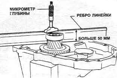
Figure 6.42. Output shaft bearing preload - dimension 'A'
7. Measure the distance from the mating surface of the clutch housing to the shoulder in the output shaft bearing bore against which the outer bearing race is installed. Repeat the measurement at three points around the shoulder and calculate the average value; write this size as 'B' (Figure 6.43).
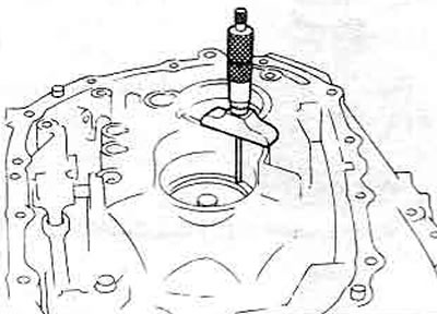
Figure 6.43. Output shaft bearing preload - dimension 'B'
8. Subtract 'A' from 'B' to get the value 'C'.
9. The required shim thickness is 'C' plus 0.25-0.31 mm and should be made up of one thick or two thin shims. Shims are available through Nissan dealers in thicknesses ranging from 0.40-1.20 mm.
10. The gasket must be installed between the left outer bearing ring and the transmission housing.
11. The preload setting can be checked by measuring the total transmission torque. See Chapter 14, paragraph 53 and Chapter 10, paragraph 63.
Input shaft lateral play
12. It is necessary to adjust the lateral clearance of the shaft if the following parts were replaced during assembly:
- Entrance vase
- Input vase bearings
- Clutch housing
- Transmission housing
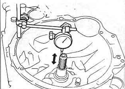
Figure 6.44. Measuring the lateral play of the input shaft
13. Install the input shaft into the clutch housing, using heavy grease to secure the grease passage at the left end.
14. Remove the input shaft adjusting shims from the transmission housing, install it in the clutch housing and tighten the mounting bolt to the tightening torque specified in the Specification.
15. Attach the gauge to the clutch housing so that the input shaft side play can be measured.
16. The thickness of the required shims will be equal to the measured lateral clearance minus 0-0.06 mm and should consist of one thick shim (where possible) or two thin shims. The shims are available through Nissan dealers in thicknesses ranging from 0.40 mm to 1.20 mm.
17. The gasket must be installed between the left outer bearing ring and the transmission housing.
18. The lateral play can be checked with a gauge immediately after the transmission assembly. A slight lateral play of up to 0.06 mm is allowed, check that there is no preload on the shaft bearings.