


Table of contents: Differential ↓ Output shaft ↓ Input shaft ↓ Transmission housing ↓ General assembly ↓
Differential
1. Install the new speedometer drive gear and stopper into the differential housing.
2. Press the inner races into the differential bearing.
3. Insert the sun gear thrust washers into the differential housing, then the sun gear itself, the planet gear thrust washers, then the planet gear. Lubricate and install the planet gear shaft.
4. Check the clearance between each gear and the differential housing. If adjustment is necessary, select thrust washers of the correct thickness. Insert a new pin to secure the planetary gear shaft.
5. Install the crown wheel. Clean the crown wheel bolt threads, tighten them and tighten them to the tightening torque specified in the Specifications.
Output shaft
6. Lubricate components generously before assembly.
7. Install the 1st gear needle bearing.
8. Install the 1st gear.
9. Install the 1st gear locking ring (photo).
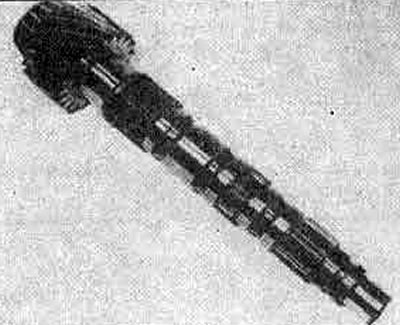
10.9A. Take the output shaft...
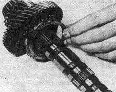
10.9V... and install the 1st gear pinion needle bearing, pinion and locking ring -
10. Install the 1st/2nd gear synchronizer and reverse gear mechanism. Install the assembly on the shaft (photo).
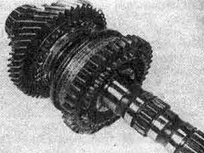
10.10. Synchronizer installed on the output shaft
11. Using grease, insert the steel ball into the hole in the shaft (photo). Never place the ball in the hole in the groove of the shaft.
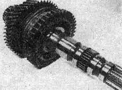
10.11 Place the steel ball in the shaft hole shown
12. Place the 2nd gear locking ring on the bevel gear.
13. Place the 2nd gear on the sleeve (photo).
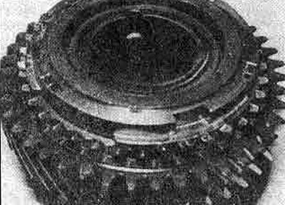
10.13. 2nd gear pinion and locking ring on 2/3 gear sleeve
14. Place the 2nd/3rd gear bushing assembly onto the shaft, slowly turning it until the ball fits into the groove (photo).
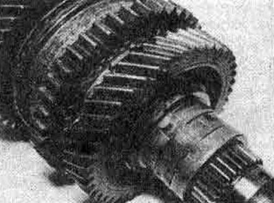
10.14. Assembling the 2/3 gear sleeve on the output shaft
15. Place the 3rd gear on the sleeve.
16. Install the blocking ring (photo).
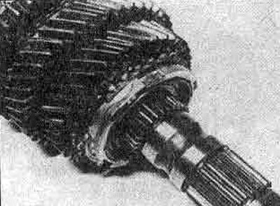
10.16. 3rd gear pinion and locking ring on the hub
17. Install the 3rd/4th gear synchronizer unit (photo).
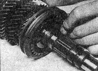
10.17. Synchronizer 3/4 gears
18. Using grease, insert the steel ball of the 3rd gear mechanism bushing into the shaft hole (photo).
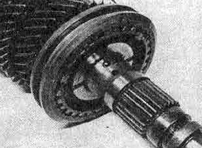
10.18. Steel ball of the 4th gear bushing on the output shaft
19. Install the 4th gear locking ring.
20. Install the 4th gear bushing by slowly turning it until the ball enters the groove (photo).
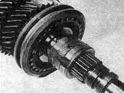
21. Install the 4th gear assembly (photo).
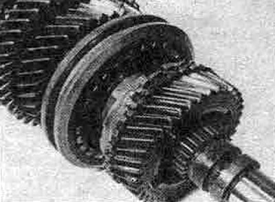
10.21. Installing the 4th gear assembly onto the hub
22. Install the 5th gear pinion. Place it carefully on the shaft using a tube (photo).
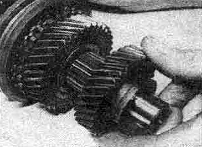
10.22. The 5th gear pinion should fit into the shaft grooves
23. Install the 5th gear thrust washer (photo).
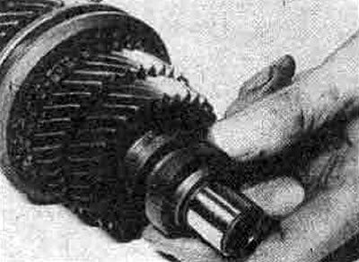
10.23. Installing the 5th gear thrust washer
24. Install the C-rings (photo). They have different thicknesses to adjust the clearance of the mechanism between the C-rings and their mounting groove.
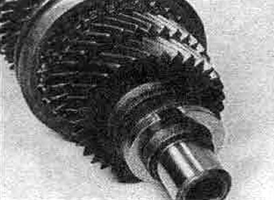
10.24. Output shaft C-rings can have different thicknesses
25. Place the C-ring holder (photo).
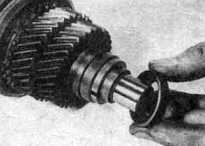
10.25. Installing the C-ring holder
26. Fit new bearing inner races to both ends of the secondary shaft. Finally, check the gear clearance again (photo).
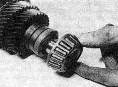
10.26A. Install the inner bearing ring...
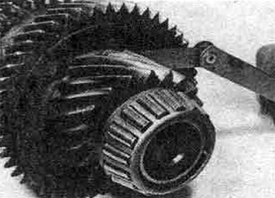
10.26V... and check the gear lateral play again
Input shaft
27. Install the needle bearing (photo).
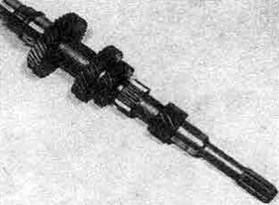
10.27A. Input shaft
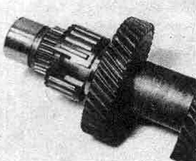
10.27B. Installing the 5th gear needle bearing
28. Install the 5th gear.
29. Install the blocking ring (photo).
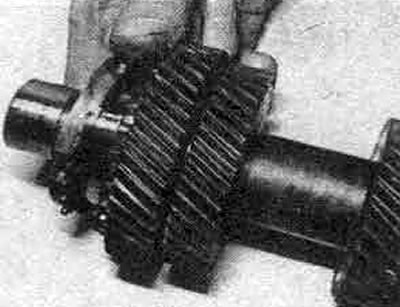
10.29. Installing the 5th gear pinion and locking ring
30. Place the synchronizer.
31. Install the lock plate and new thrust ring to hold the assembly in place (photo). The thrust rings come in different thicknesses to adjust the play in the mechanism.
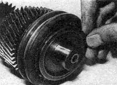
10.31A. Install the 5th gear synchronizer and lock plate
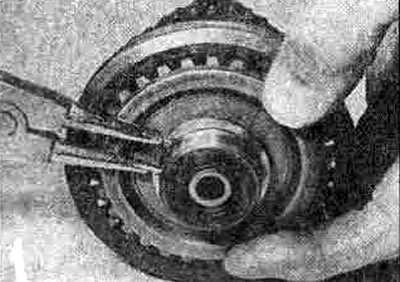
10.31B Install a new snap ring to secure the assembly
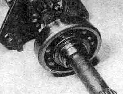
32. Install the bearing retainer and new right bearing, then install the gasket. Select a new thrust washer of the required thickness and install it. Check that the clearance between the thrust washer and the groove is within the specified limits (photo).
33. Heat the clutch housing, install a new seal (photo).
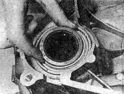
10.33. Differential side bearing seal (drive shaft)
34. When installing the secondary shaft bearing outer race, be sure to install the oil channel first. Align it so that the groove is aligned with the oil pocket (photo) and check that it remains in this position when installing the outer race.
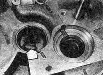
10.34. Removing the lubrication channel (marked with an arrow) must be aligned as shown
35. Install the offset fork shaft sleeve.
36. Install new seals.
Transmission housing
37. If the differential bearings were replaced, install a new outer bearing race without a gasket. Install a new oil seal.
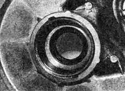
10.37. The bearing preload gasket must be in the transmission housing
38. Fit the new O-ring with sealant and install the cover, tighten the bolts to the torque specified in the Specifications.
39. If the input shaft needle bearing was replaced, install a new small plug into the hole in the crankcase, covering the outer surface with sealant.
40. Install the oil trough (photo).
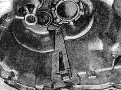
10.40 Install the oil pan into the transmission housing
41. Install the reverse light switch.
General assembly
42. Install the new O-ring (photo) and lubricate it, then install the reverse lock plunger assembly and tighten the screws to the torque specified in the Specifications.
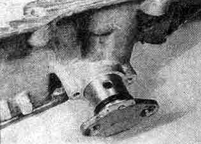
10.42 Replace the O-ring when installing the reverse lock plunger assembly
43. Install the small ball detent, then the larger ball and spring (photo).
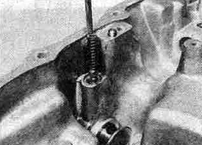
10.43. Ball detents and spring
44. Lubricate and install the rod. If a new seal is already installed, wrap the sharp edges of the rod with adhesive tape to protect the sealing lips. Assemble the lever and lock, install them on the rod, insert the new cylindrical pin (photo). Use the marks made during dismantling to properly align the rod. The cuts should be aligned with the hole in the retainer assembly.
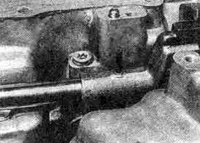
10.44. Hammer in a new cylindrical pin
45. The pressure of the reverse lock spring can be adjusted by installing plugs of different lengths; standard plug - 13.3 mm long (photo). Check the clamp pressure as follows.
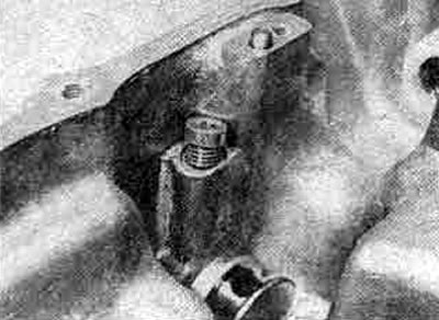
10.45. The plug of the reverse lock spring has different lengths
46. First install the initial plug, tighten it to the tightening torque specified in the Specification. Using a G-clamp, secure a suitable rod to the crosshead (see figure 6.15).
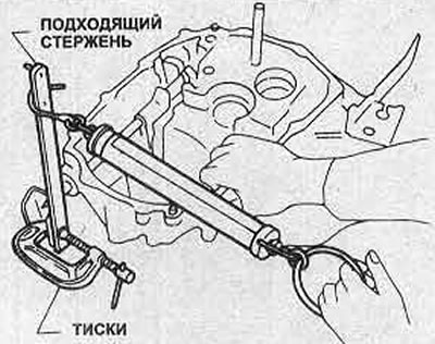
Figure 6.15. Checking the force of the reverse lock spring
Then, using a spring balance set at a known distance from the center of the rod, measure the force of the clamp. It should be 10.3-12.7 Nm.
47. If the measured force is too weak, install a longer plug; if the force is too great, install a shorter plug. If the installation is correct, apply blocking compound to the threads of the selected plug and install it, tightening the tie rods with the force specified in the Specification.
48. Install the differential assembly. Install the speedometer drive gear assembly as described in Chapter 4 of this Section.
49. Install the input shaft and the reverse gear intermediate shaft at the same time (photo).
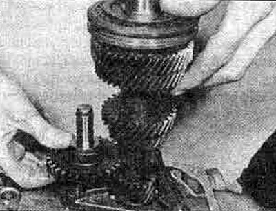
10.49 Install the input shaft and reverse gear (note the gasket)
50. Install the oil pocket (photo).
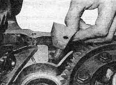
10.50. Installing the oil pocket
51. Install the gasket on the intermediate reverse gear.
52. Place the triangular separator. Apply locking fluid to the screw threads, tighten them to the tightening torque specified in the Specification.
53. Install the output shaft, carefully engaging the teeth with the input shaft gears. Push both synchronizer bushings and clamp the reverse intermediate shaft (photo).
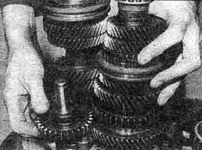
10.53. Installing the output shaft
54. Install the rod retainer bushing, ball and spring into the hole (photo).
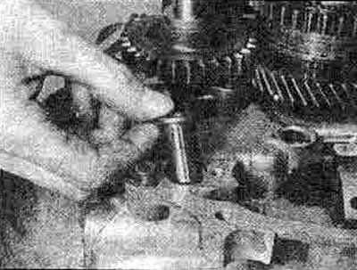
10.54A. Install the retainer sleeve into the hole...
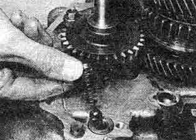
10.54B... then the ball and the spring
55. Use grease to secure the switch covers to the control suspension (photo).
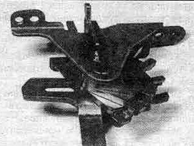
10.55. Control and switch cover hanger
56. Assemble the steering hanger and 1/2 shift fork and install them (photo). Tighten the steering hanger bolts to the specified torque Specification.
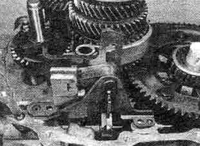
10.56A Place the control hanger on the 1/2 gear shift fork...
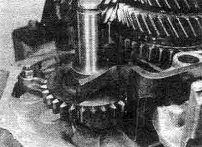
10.56V... and intermediate shaft of reverse gear
57. Now install the 3/4 shift fork and then the 5th gear shift fork (photo).
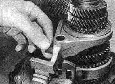
10.57A. Install the 3/4 gear selection fork —
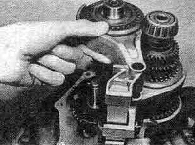
10.57V... and the 5th gear selection fork
The article is located on the website NISSANBOOK.RU
58. Pass the fork shaft through the fork, the coil spring should fit into the recess at the lower end of the shaft (photo).
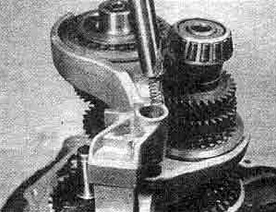
10.58. Fix the coil spring on the offset fork shaft with grease
59. With the clutch housing on a bench in an upright position, apply sealant to the mating surfaces of the transmission case and clutch housing.
60. Lower the body back into place.
61. Install the mounting bolt, tighten it to the specified tightening torque Specification.
62. If it is necessary to adjust the output shaft bearing preload, install the left-hand bearing outer race and continue as described in Chapter 11 of this Section. When the correct thickness of shim is selected, lock the outer bearing race with grease, then the shim. Install the cover as described in step 38 above.
63. The correct adjustment of the transmission can be checked if special equipment for measuring the total torque is available. This requires a special tool number KV38105900, forked at one end to fit over the planetary shaft. An adapter for a suitable torque wrench is installed at the other end (figure 6.16). The correct torque will be in the specified range if new bearings were installed, and slightly less if old bearings were installed.
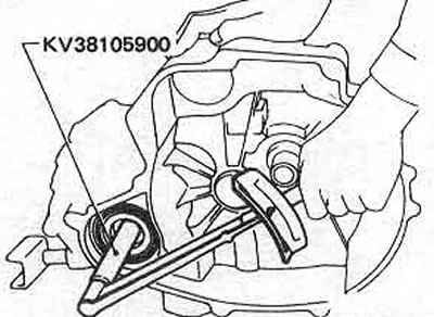
Figure 6.16. Measuring Total Transmission/Differential Torque
64. Install the clutch release mechanism components as described in Section 5.
65. Rotate the input shaft to check that all gears can be engaged relatively easily.