


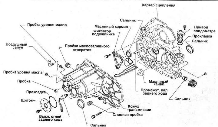
Figure 6.6. Model selector mechanism - 1.6 liters
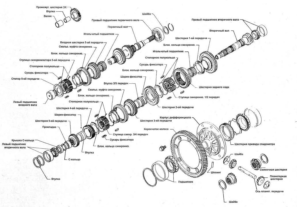
Open a larger image in a new tab »
Figure 6.7. Internal components of the gearbox of the 1.6 liter model
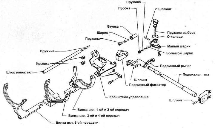
Figure 6.8. Gear selection details for the 1.6 liter model
1. After removing the transmission from the vehicle, clean any dirt from the outer surface using a water-soluble solvent and a stiff brush.
2. Remove the clutch release mechanism components from the clutch housing. Clean the clutch housing from the inside.
3. Unscrew the bolts connecting the transmission housing to the clutch housing and separate them (Figure 6.9). Tilt the gear housing slightly to prevent the 5th gear shift fork from jamming.
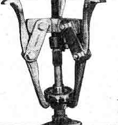
Figure 6.9. Removing the transmission housing
4. Remove the reverse intermediate gear gasket, remove the offset fork shaft from the fork, note the coil spring in the clutch housing (photo).
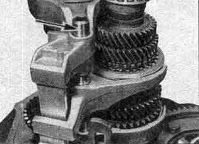
8.4 Remove the offset fork shaft (marked with an arrow)
5. Remove the 5th and 3rd/4th gear shift forks (Figure 6.10). Make sure that the switch covers installed above the end of the control suspension arm do not move; two on models before February 1988, three on later models.
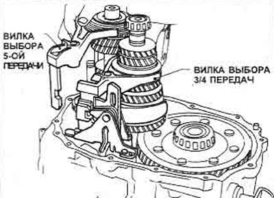
Figure 6.10. Removing the 5th and 3/4 gear selection forks
6. Unscrew the bolt from the control suspension, remove it together with the 1st/2nd gear mixing fork. Remove the traction lock spring, ball and bushing from the hole at the bottom (photo).
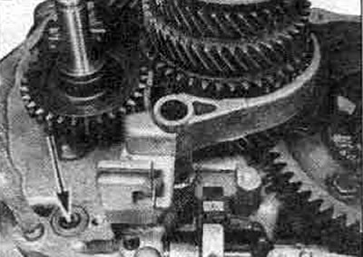
8.6. After removing the control suspension, you can remove the retainer spring, ball and bushing (marked with an arrow)
7. Remove the output shaft; do not tilt it when doing this. Unscrew the mounting screws (photo) and remove the speedometer drive gear assembly, then lift the differential assembly.
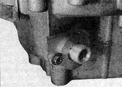
8.7. Speedometer gear assembly mounting screw
8. Remove the three bolts securing the triangular input shaft bearing retainer by lifting the reverse idler gear (photo). Position the clutch housing so that the input shaft is horizontal, remove the shaft with the bearing retainer and the reverse idler gear from the clutch side. Do not attempt to remove the reverse idler gear from the shaft.
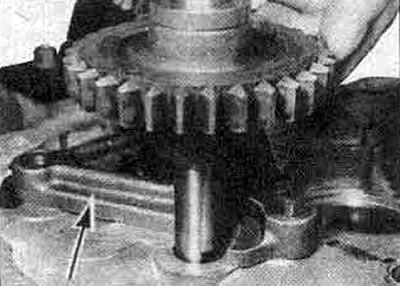
8.8. The input shaft separator is secured with three bolts
9. Remove the oil pocket from the recess.
10. Before disassembling the selector mechanism, mark the location of the rod and lever with paint, then remove the cylindrical pin from the rod. Remove the rod from the lever. Remove the oil seal from the rod. They must be replaced (photo).
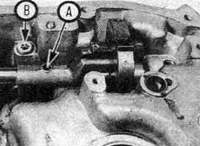
8.10A. Mark the position of the lever on the rod before knocking out the cylindrical pin "A", note the location of the reverse lock plug "B"
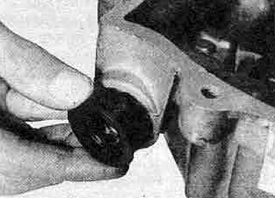
8.10B. Replace the seal of the rod of the selection mechanism
11. Unscrew the reverse lock plug and remove the lock springs and balls.
12. Remove the two screws (photo) and remove the reverse lock plunger assembly. Clutch housing
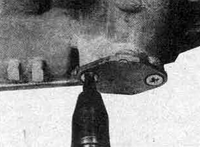
8.12. Removing the reverse lock plunger assembly screws
13. Replace the input shaft, differential and tie rod seals as described previously.
14. Do not disturb the switch plug (photo) unless necessary. If it is disturbed, apply grease to the threads and tighten it to the tightening force specified in the Specification. Do the same with the two plugs in front of the transmission housing.
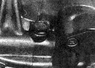
8.14. Neutral gear switch plug
15. If the output shaft bearing outer races or differential outer races need to be removed, a bearing puller should be prepared or contact the dealer (photo). If the output shaft bearing lubrication channel is broken, a new one should be installed during assembly.
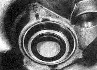
8.15. Special extractor for removing outer rings of differential bearing
16. The offset fork shaft bushing can be removed by heating the clutch housing and using a special extractor. The same applies to the bushing at the opposite end of the shaft, in the transmission housing. Transmission housing
17. Unscrew and remove the reversing light switch.
18. Remove the oil pan.
19. If the input shaft needle bearing needs to be replaced, remove the smaller plug from the transmission housing. This can be done by drilling a hole in the plug, then screwing a screw into it. Pull the plug out using the screw, then push the bearing out. Do not touch the large plug (photo).
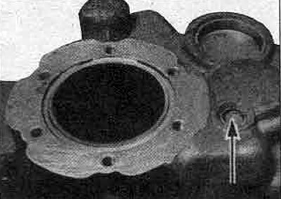
8.19A. Remove the smaller plug from the transmission housing...
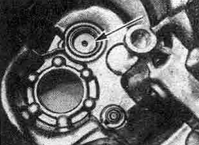
8.19B... knock out the input shaft needle bearing
20. Unscrew the round cover on the casing, remove the adjusting gasket of the driven shaft bearing. To replace the driven ZIL bearing, push out the old one and seat the new one. Replace the cover seals.
21. A special tool is required to remove the outer race of the differential bearing. See item 15 above, but note the presence of a preload adjusting shim. Replace the seal as described in Chapter 5 of this Section.
Input shaft
22. Measure and record the 5th gear clearance (Figure 6.11). Remove the thrust ring and 5th gear retaining plate.
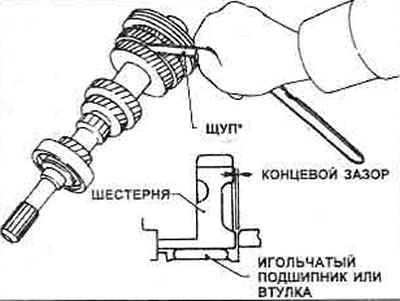
Figure 6.11. Measuring the lateral clearance of the gear - the 5th gear gear of the input shaft is shown
23. Remove the 5th gear pinion with synchronizer and the needle bearing from inside the pinion.
24. The input shaft cannot be disassembled further than removing the right bearing by first removing the thrust ring and gasket. Remove the bearing from the shaft (photo). Discard both thrust rings.
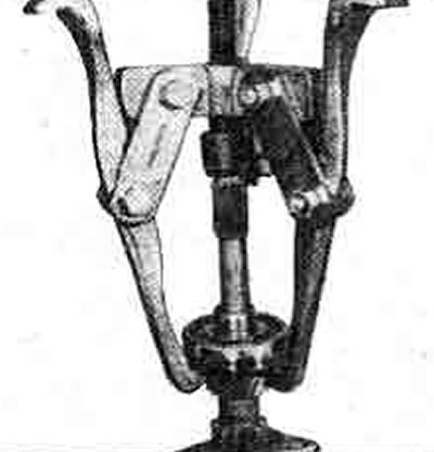
8.24. Removing the right bearing from the input shaft
Output shaft
25. Measure and record the clearance of the 1st, 2nd, 3rd and 4th gears.
26. Remove the inner bearing races from each end of the shaft. Remove the bearings.
27. Remove the C-ring holder, C-ring and thrust washer. Remove the 5th gear mechanism gear (photo).
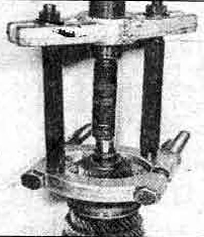
8.27. Removing the 5th gear from the output shaft
28. Remove the 4th gear pinion, gear bushing and steel locking ball.
29. Remove the locking ring.
30. Remove the 3rd/4th gear synchronizer.
31. Remove the 3rd gear.
32. Remove the 2nd/3rd gear bushing.
33. Remove the steel locking ball.
34. Remove the 2nd gear.
35. Remove the locking ring.
36. Remove the 1st/2nd gear synchronizer with the reverse gear mechanism (straight teeth on synchronizer sleeve) together with the gear of the 1st gear mechanism. The synchronizer hub is clamped on the shaft and the best way to remove the assembly is to use an extractor (photo).
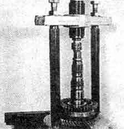
8.36. Removing the 1/2 gear synchronizer and 1st gear from the output shaft
37. Remove the 1st gear needle bearing.
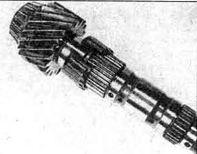
8.37. Needle bearing of 1st gear pinion of output shaft
Differential
38. Unscrew the crown wheel from the differential housing.
39. Press out the planetary gear shaft pin and remove the shaft.
40. Remove the planet and sun gears and their thrust washers. Store each thrust washer with its corresponding mechanism, labeling each mechanism.
41. Disconnect the speedometer drive gear (photo), remove the differential bearings. Remove the drive gear stopper.
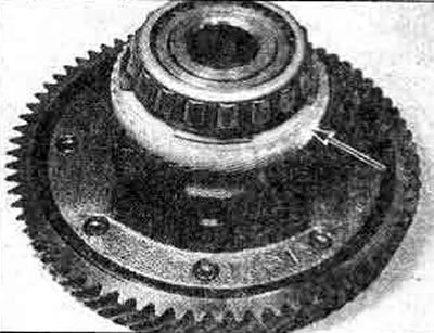
8.41. Speedometer drive gear (marked with an arrow) must be disconnected to remove the differential bearing