


Table of contents: Clutch housing ↓ Transmission housing ↓ Input shaft ↓ Output shaft ↓ Differential ↓
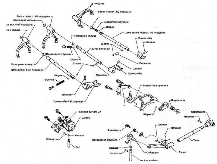
Figure 6.18. Selector mechanism - model 1.8 (including Turbo) and 2.0 liters
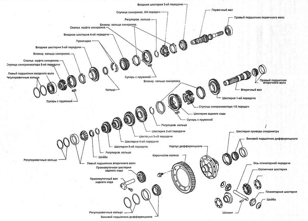
Open a larger image in a new tab »
Figure 6.19. Transmission Internal Components - 1.8 Liter Models (including Turbo) and 2.0 liter models
1. With the transmission removed from the vehicle, clean off any dirt with water or kerosene and a stiff brush.
2. Remove the clutch release mechanism components from the clutch housing.
3. With the transmission mounted on the clutch housing surface, first remove the gear position switch. See Chapter 5 of this Section.
4. Referring to Figure 6.21, unscrew the reverse gear intermediate shaft bolt, 3rd/4th gear lock plug and 1st/2nd gear lock plug. Remove the lock springs and ball; marking them and storing them separately with the corresponding plugs. Some models may have a dual 3rd/4th gear locking spring.
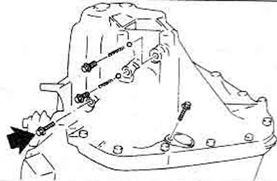
Figure 6.21. Unscrewing the reverse intermediate shaft bolt (marked with an arrow), plugs of the clamps and the bolt of the position switch
5. Unscrew the bolts, lift the transmission housing. Remove the input shaft left bearing gaskets and the lubrication channel.
6. If necessary, displace the position switch from the transmission housing.
7. Select 4th gear, extend the reverse gear intermediate shaft, remove the reverse gear from the reverse lever assembly.
8. Pull out the fastening button, use a hammer and punch to knock the plug out of the reverse gear lever shaft (figure 6.22). Discard the O-ring and have a new one ready.
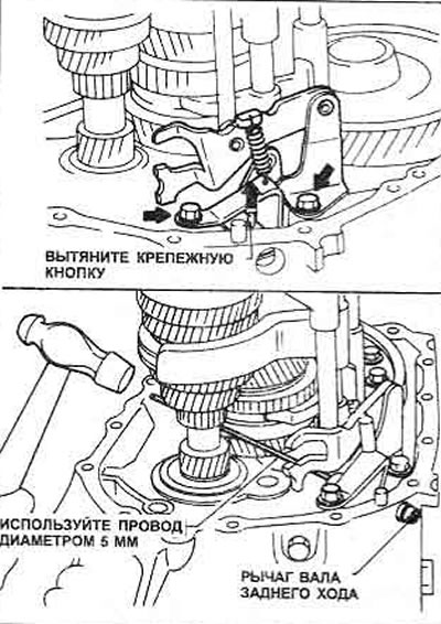
Figure 6.22. Knock out the reverse shaft lever mounting pin and remove the shaft
9. Unscrew and remove the reverse gear lever assembly and steel ball retainer.
10. Unscrew the 5th/3rd gear lock plug, remove the spring and ball (Figure 6.23).
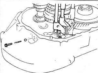
Figure 6.23. Removing the 5/3X gear lock plug
11. Remove the retaining rings from the 5th and 3rd/4th gear shift forks.
12. Remove the roll pins securing the fork hangers to the 5th/3rd and 3rd/4th gear fork rods (Figure 6.24).
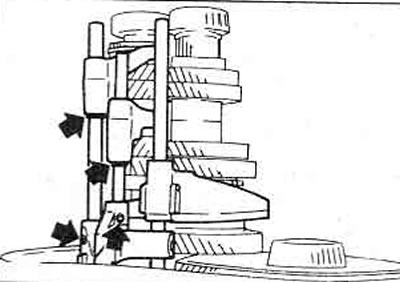
Figure 6.24. Removing the 5/3 and 3/4 gear fork rods - the cylindrical pins are marked with arrows
13. Pull out the 5/3 and 3/4 gear fork rods, remove the offset and suspension forks.
14. Grasp the primary and secondary shaft assemblies and lift them out of the clutch housing, along with the offset fork and 1st/2nd gear linkage (Figure 6.25). Also lift the differential assembly.
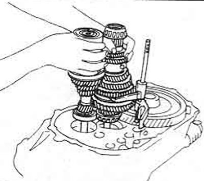
Figure 6.25. Removing the input and output shaft with 1/2 gear fork, rod and suspension
15. Remove the balls and plungers from the clutch housing.
16. Unscrew the reverse lock assembly (Figure 6.26).
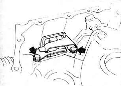
Figure 6.26. Removing the reverse lock assembly
17. Remove the selector shaft mounting pin, remove the shaft (Figure 6.27 and 6.28) and remove the selector.
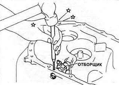
Figure 6.27. Removing the leash roller fastening button
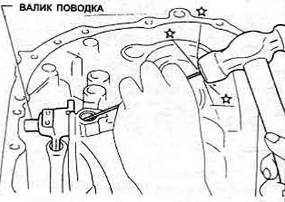
Figure 6.28. Knocking out the leash roller
18. Unscrew the drain plug, push out the lever mounting pin (Figure 6.29).
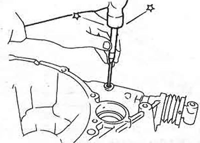
Figure 6.29. Removing the lever mounting button
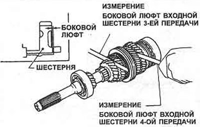
Figure 6.30. Measuring lateral play - input shaft 3rd and 4th gears shown
19. Remove the rod and lever.
Clutch housing
20. Replace the input shaft, differential and tie rod seals as described previously.
21. Refer to Chapter 8 of this Section for details on removing and installing the output shaft and/or differential bearing outer races.
22. Remove and clean the oil pocket and magnet.
Transmission housing
23. Remove and install the differential seal.
24. Remove and install the offset fork shaft sleeve.
25. Remove and install the offset fork shaft bushing as described in Chapters 8 and 9.
26. Remove and clean the oil pan.
27. Do not disturb the plugs unless absolutely necessary. If necessary, they can be removed as described in Chapter 8 and install new ones as described in Chapter 9.
Input shaft
28. Using a feeler gauge, measure the play of the 3rd, 4th and 5th gears. Record the values obtained.
29. Several parts are pressed into the input (and on the weekend) shaft. It is preferable to have a bearing puller (see photos 8.27 and 8.36) to remove such parts. If there is no puller, the component must be carefully clamped in a large vice and the shaft must be knocked out with a soft mallet.
30. Pull off the left bearing.
31. Then pull off the 5th gear pinion and synchronizer.
32. Remove the retaining ring and thrust washer, then the 4th gear gear.
33. Remove the thrust ring.
34. Pull off the 3rd gear pinion and the 3rd/4th gear synchronizer.
35. Remove the right bearing if necessary.
Output shaft
36. Using a feeler gauge, measure the play of the 1st and 2nd gears and record the results.
37. Press out the inner ring of the left bearing.
38. Remove the thrust washer, take out the thrust ring.
39. Press out the 4th and 5th gears.
40. Similarly, press out the 2nd and 3rd gears together.
41. Remove the thrust ring.
42. Pull together the 1st gear pinion and synchronizer (which includes the reverse gear) 1st/2nd gear.
43. Tighten the right inner bearing race if necessary.
Differential
44. Remove the differential as described previously (these models do not have a speedometer drive gear lock).