


Table of contents: Differential ↓ Secondary shaft ↓ Input shaft ↓ Transmission housing ↓ Clutch housing ↓ General assembly ↓
Differential
1. Assembly of the differential is similar to that described for 1.6 liter models.
Secondary shaft
2. Install the right inner bearing race.
3. Install the 1st gear pinion and locking ring.
4. Correctly oriented (figure 6.31), install the 1st/2nd gear synchronizer.
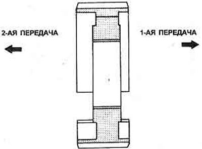
Figure 6.31. Correct installation of the 1/2 gear synchronizer hub
5. Place the sleeve on the hub (Figure 6.32). Then the 2nd gear locking ring.
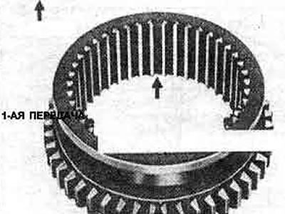
Figure 6.32. Location of the spring insert on the 1/2 gear synchronizer sleeve
6. Install the synchronizer mounting thrust ring. They are available in different thicknesses 1.95 mm - 2.10 mm with a step of 0.05 mm. Select the thrust ring so that the play is within the specified limits.
7. Install the 2nd gear gears, then 3rd, 4th and 5th.
8. Install the 5th gear retaining ring. They also come in different thicknesses to adjust the clearance between the retaining ring and the groove.
9. After selecting and installing a thrust ring of the correct thickness, install the thrust washer.
10. Install the left inner bearing race.
11. Measure the lateral play of the 1st and 2nd gears again, check that it is within the specified limits.
Input shaft
12. Install the right inner bearing race.
13. Install the 3rd gear pinion and locking ring.
14. Correctly oriented (figure 6.33), install the 3/4 gear synchronizer hub.
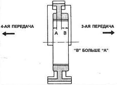
Figure 6.33. Correct installation of the 3/4 gear synchronizer hub
15. Using heavy grease, secure the three inserts into the grooves of the synchronizer sleeve (figure 6.34), install the sleeve into the hub, then the 4th gear locking ring.
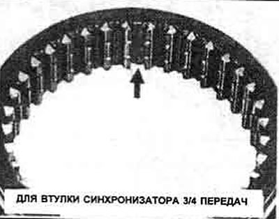
Figure 6.34. Location of the spring insert on the 3/4 gear synchronizer sleeve
16. Install the synchronizer mounting thrust ring. They are available in different thicknesses, with a step of 0.05 mm from 1.95 mm to 2.10 mm. Select the required thickness of the thrust ring based on the measured play.
17. Install the 4th gear.
18. The thrust washers of the 4th gear also have different thicknesses, with a step of 0.025 mm from 4.500 mm to 4.575 mm. Select a pair of washers so that the clearance between the thrust washers and the groove is within the specified limits.
19. Install the thrust washer retaining ring (Figure 6.35).
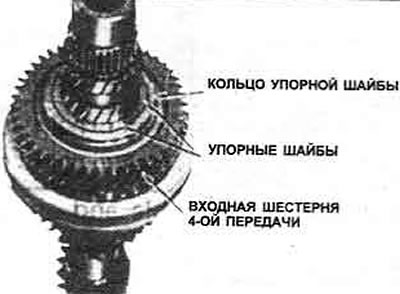
Figure 6.35. Installing thrust washers and 40th gear ring
20. Install the 5th gear pinion and locking ring.
21. Install the 5th gear synchronizer hub.
22. Using heavy grease, secure the three insert springs into the grooves of the synchronizer sleeve (figure 6.36), install the sleeve on the hub.
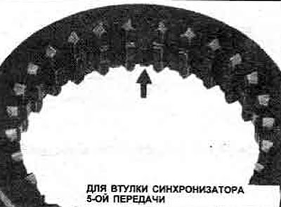
Figure 6.36. Location of the spring insert on the 5th gear synchronizer sleeve
23. Install the left bearing. See point 2 above, but make sure that pressure is applied only to the inner race of the bearing.
24. Measure the lateral play of the 3rd, 4th and 5th gears again.
Transmission housing
25. If the differential side bearings or the secondary shaft bearing have been replaced, the bearing preload must be adjusted. Install the outer races.
26. Don't forget to install the oil gutter.
Clutch housing
27. Install the oil seal.
28. Install the secondary shaft and the outer rings of the differential side bearings.
29. Don't forget to install the oil pocket and magnet.
General assembly
30. Place the lever in the clutch housing, insert the rod. Secure the rod in the lever with a pin (Figure 6.37). Install the drain plug.
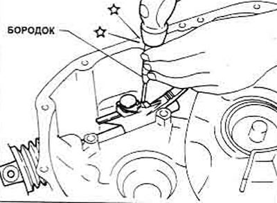
Figure 6.37. Installing the lever mounting pin
31. Turn on the selector with the lever, insert the selector shaft, securing it with a pin.
32. Install the reverse lock assembly and tighten the bolts to the torque specified in the Specifications.
33. Install the differential assembly.
34. Install the hanger to the 1st/2nd shift fork rod and secure them with the pin. Install the 1st/2nd shift fork to the rod and secure them with the pin. Position the fork on the 1st/2nd synchronizer sleeve.
35. Place the input and secondary shaft assemblies together and install them into the clutch housing, being careful not to damage the input shaft seal.
36. Insert the locking ball, plunger, and 1st/2nd gear fork rod retaining ball (Figure 6.38).
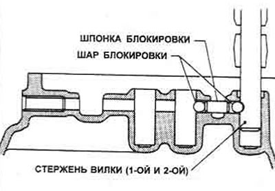
Figure 6.38. 1/2 gear shift fork locking balls and plunger rod
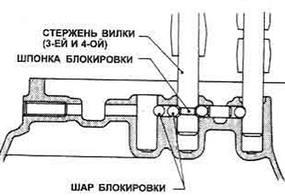
Figure 6.39. Locking balls in the 3/4 shift fork rod
37. Position the 3rd/4th gear shift fork on the 3rd/4th gear synchronizer sleeve of the input shaft.
38. Position the suspension, insert the 3rd/4th gear fork rod. Align the holes and insert the mounting pin. Place a new stopper under the offset fork.
39. Insert the plunger and two locking balls of the 3rd/4th gear fork linkage.
40. Position the 5th gear shift fork on the 5th gear synchronizer sleeve of the input shaft.
41. Position the suspension. Insert the 5th gear fork rod. Align the holes and insert the mounting pin. Install the new stopper.
42. Insert the 5th/REX ball detent and spring, tighten the detent plug to the tightening torque specified in the Specifications.
43. Install the reverse gear lever assembly and steel ball, tighten the bolts to the tightening torque specified in the Specifications.
44. Insert the reverse shaft, install the pin.
45. Engage 4th gear. Place the reverse idler gear, then insert the shaft, position the end of the shaft assembly as shown in Figure 6.40.
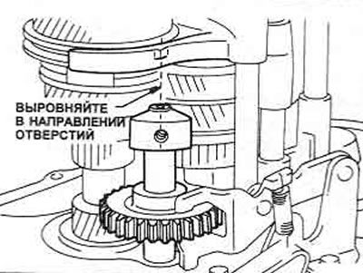
Figure 6.40. Correct alignment of the reverse intermediate shaft
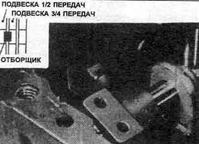
Figure 6.41. Location of the selector/suspension when installing the transmission housing
46. Lubricate the left input shaft bearing linings and place them in the housing.
47. Before installing the transmission cover, place the selector either to the 1st/2nd gear fork link hanger or between the 3rd/4th and 1st/2nd gear hangers.
48. Apply sealant to the mating surfaces of the transmission housing and clutch housing.
49. Lower the gearbox housing onto the clutch housing, tighten the bolts to the tightening torque specified in Specifications.
50. Insert the 1st/2nd and 3rd/4th gear ball detents and springs. Tighten the plugs to the tightening torque specified in Specifications.
51. Install the reverse gear intermediate shaft bolt, apply sealant to the threads of the reverse gear intermediate shaft bolt and tighten it to the tightening torque specified in Specifications.
52. Install the gear selector switch.
53. Check the various adjustments (see Chapter 15), measuring the total torque of the transmission. Proceed as described in Chapter 10, item 63, note that now tool number K.V38106500 is required.
54. Install the clutch release mechanism components as described in Section 5.
55. Rotate the input shaft to check that all gears engage with relative ease.