


Table of contents: Differential bearing preload ↓ Output shaft bearing preload ↓
Differential bearing preload
1. If any of the following parts have been replaced, the bearing preload must be adjusted:
- Differential housing
- Differential side bearings
- Clutch housing
- Transmission housing
2. Install the differential into the clutch housing, check that the outer bearing race is installed to the transmission case without the adjusting shim, and install the transmission case. Tighten the mounting bolt to the tightening torque specified in the Specification.
3. Special tools are required - a gauge and a stand (nissan part number KV38106000 but any suitable clamp or stand can also be used) and the split tool KV3 8105900 (see Chapter 10, paragraph 63). The latter can be replaced with a piece of wooden dowel thin enough to fit inside the sun gear and against the planet shaft.
4. Place the gauge against the differential housing, move the differential assembly all the way up and down and record the total displacement (figure 6.17).
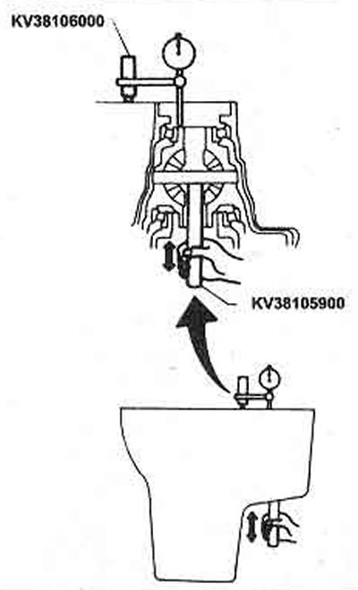
Figure 6.17. Measuring differential lateral play
5. The required shim thickness is the measured value plus 0.29-0.35 mm and should be made up of one or two shims. The shims are available through Nissan dealers in the thickness range 0.44 mm - 0.88 mm.
6. To ensure proper engagement of the teeth, a spacer must be installed between the left side of the differential bearing outer race and the transmission housing.
7. The preload setting can be checked by installing the differential assembly into the clutch housing only and installing the transmission housing. Tighten the mounting bolt to the specified torque Specification.
8. Follow the procedures given in Chapter 10, item 63, measure only the differential torque. It should be in the specified range if new bearings are installed, and slightly less if old ones are installed, and should not differ by more than 1.0 Nm.
Output shaft bearing preload
9. If any of the following parts have been replaced, the bearing preload must be adjusted:
- Output shaft
- Output shaft bearings
- Clutch housing
- Transmission housing
10. Install the output shaft into the clutch housing. Check that both bearings are fully seated on the shaft and remove the O-ring cover and seal, spacer, adjusting shim and outer race of the left bearing from the transmission housing. Install the transmission housing onto the clutch housing, tighten the mounting bolt to the specified torque Specification.
11. Place the outer ring on the end of the shaft and tap it to ensure complete installation (photo).
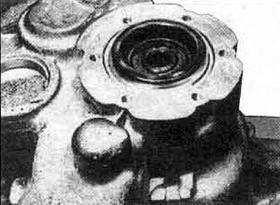
11.11 Install the outer ring and hammer it firmly onto the bearing
12. Measure the distance from the transmission case surface to the outer ring, then select the gasket (preferably just one), which will reduce the distance to 2.25-2.30 mm. The spacers are available in a thickness range of 0.10 mm - 1.00 mm in 0.05 mm increments.
13. Once the correct thickness shim has been selected, place it against the outer ring with the shim (photo), the two shims together should give the specified bearing preload when the round cover is secured.
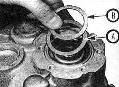
11.13. Output shaft bearing preload adjusting shims A and B
14. Install the round cover as described in Chapter 10 of this Section.
15. If special equipment is available, the total torque of the transmission can be measured. See Chapter 10, paragraph 63.