


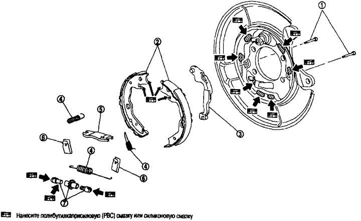
Parking brake shoe. 1. Anti-bounce pin; 2. Parking brake shoe; 3. Crank lever; 4. Return spring; 5. Brake spacer; 6. Spring; 7. Regulator.
Removal and installation
Removal
Caution: Clean the parking brake shoes and mudguard with a vacuum cleaner. Do not use compressed air.
1. Remove the rear wheels.
2. Remove the brake disc with the parking brake lever in the fully released position. See above.
Attention:
- If the brake disc is to be reused, make alignment marks on the brake disc and the wheel hub and wheel bearing assembly before removing it.
- Do not drop the brake disc.
3. If the brake disc does not come off, do the following:
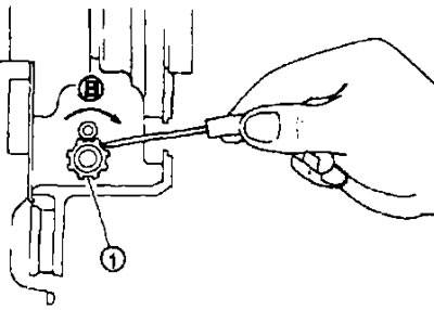
a. Secure the brake disc with the wheel nuts and remove the plug from the adjuster hole.
b. Using a flat-blade screwdriver, turn the adjuster (1) in direction (B), pull back and loosen the brake shoes.
4. Remove the spring anti-bounce pins and return springs.
Caution: Do not drop removed components.
5. Remove the brake spacer, adjuster, parking brake shoes and bell crank.
Attention:
- The front and rear parking brake shoes are made of different materials, do not mix them up when removing.
- Do not drop removed components.
6. Mudguard removal operations. See chapter "Rear axle and suspension".
Installation
Installation is carried out in the reverse order of removal.
- Apply polybutyl caprylic (PBC) grease or silicone grease to the splash shield and brake pads.
Caution: The front and rear parking brake shoes are made of different materials. Do not mix them up when removing and installing.
- Set the regulators so that when they are turned in the direction indicated by the arrow, the threaded part appears.
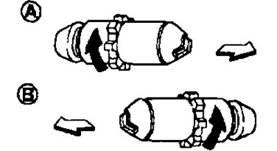
A: For the right wheel brake.
B: For the left wheel brake.
 : In front of the car.
 : The regulator is extended.
- Shorten the regulator by rotating it.
- After disassembly, apply polybutyl caprylic (PBC) grease or silicone grease to the threads.
- Check for grease on the sliding surface of the brake shoe and on the inner surface of the drum. If grease gets on the surfaces, wipe it off.
Checking and adjusting
Check after removal
Checking the thickness of the friction lining.
Check the thickness (A) of the friction lining.
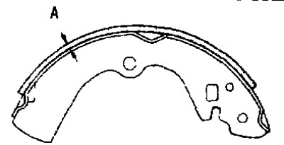
Standard thickness: See below. "Technical data and specifications".
Wear limit: See below. "Technical data and specifications".
Checking the inner diameter of the drum.
Check the inner diameter (B) of the drum.
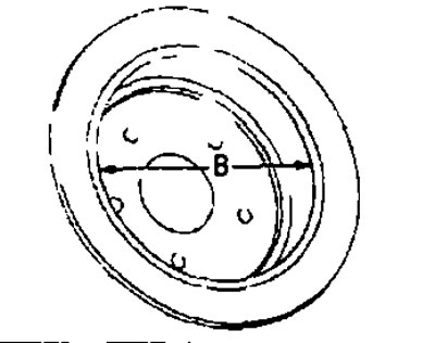
Standard Inner Diameter: See below. "Technical data and specifications".
Maximum internal diameter: See below. "Technical data and specifications".
Other checks
Check and if any deviations from the norm are found, replace:
- is there excessive wear, damage or peeling of the friction lining?;
- is there excessive wear or damage on the sliding surface of the pad;
- is there excessive wear, damage or corrosion on the anti-chatter pin;
- are the springs and return springs sagging?;
- is there any excessive wear, damage or corrosion?;
- is there excessive wear, damage or corrosion on the brake strut;
- does the regulator move freely;
- is there excessive wear, damage or corrosion on the crank arm;
- perform a visual inspection of the drum from the inside to ensure there is no excessive wear, cracks or damage;
- using a pair of calipers, check the inside diameter of the drum.
Adjustment after installation
- Adjust the length of the parking brake lever stroke to the required number of clicks.
- If the brake pads and/or brake discs are replaced or if the brakes do not operate correctly, perform the bedding-in procedure as follows:
1. Adjust the length of the parking brake lever stroke to the required number of clicks.
2. Run in the parking brake by driving the vehicle under the following conditions:
Moving forward.
- Vehicle speed: approx. 40 km/h (constant in forward direction)
- Brake pedal force approx. 130 N (13.3 kg) (permanent)
- Time approx. 10 sec.
Caution: To avoid overheating the friction lining, allow it to cool for approximately 5 minutes after each running-in cycle.
3. After running-in, check the stroke length of the parking brake lever. If it is different from the standard, readjust.