


Note: Dust generated by brake wear and deposited on brake components may contain asbestos. Do not blow it away with compressed air or inhale it; it is dangerous to your health. Wipe off dust using a clean dry cloth, working in a well-ventilated area, then throw away the cloth. Although the main friction materials do not contain asbestos, take precautions.
Don't skimp on buying brake components. Brake pads should always be replaced to ensure consistent braking performance. For this reason, only buy components from Nissan dealers.
1. Place the car on a level surface, apply the handbrake and select reverse gear first (manual transmission) or "R" (automatic transmission). Block the front wheels. Loosen the wheel nuts, jack up the rear of the car, and support it with jack stands for safety. Remove the wheel and release the handbrake completely.
2. Loosen the handbrake cable bolt on the caliper (photo) and disconnect the cable and pipe from the lever. Remove the clamp from the spring securing the flexible hose to the shock absorber.
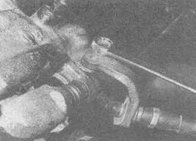
23.2. Unscrewing the handbrake cable mount from the rear right brake caliper
3. Move the caliper body outward so that the piston can be inserted into the cylinder.
4. Remove the rear caliper guide pin bolt, using a thin open-ended wrench if necessary. Rotate the caliper body upward to remove the brake pads (photo). Do not press the brake pedal until the caliper is assembled.
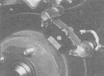
23.4. Rotate the caliper body upwards to expose the pads - note the location of the shim on each pad
5. Handle the pads attached to the metal base of each pad with care. Mark them so that they are reinstalled in their original position. Pay attention to the uniformity of wear of the brake pads.
6. First, measure the thickness of the friction material remaining on each brake pad. If it is worn down to the minimum thickness or less at any point, all four rear brake pads must be replaced. Also, the pads must be replaced if they are contaminated with grease, as it is almost impossible to degrease them properly.
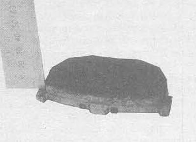
23.6. Measuring the thickness of the brake pad friction material - replace all four pads if at least one is worn
Material borrowed from the website: nissanbook.ru
7. If the pads are still serviceable, clean them using a clean wire brush.
8. If there is any uncertainty about the caliper's ability to slide in the mounting suspension, remove it, clean it, and lubricate the guide pins as described above. Check the brake disc.
9. When assembling, put on the anti-rattle springs by lubricating them with a thin layer of organosilicon grease - or RVS (Paly Butyl Cuprysil) based on high temperature brake component lubricant. Do not allow the lubricant to contaminate the friction material. Install the pads to the caliper mounting bracket so that the friction material is against the disc.
10. If new pads are being installed, the piston must be pulled into the cylinder to create space for the pads. Using long round-nose pliers and inserting them into the special cuts in the piston, screw the piston clockwise (looking at the piston from the side of the car) until it snaps into place. Be careful not to damage the dust seal when turning. Fill the master cylinder reservoir to the "Max" mark.
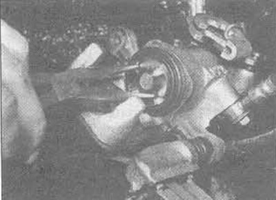
23.10. Use pliers to secure the caliper piston - turn it clockwise
11. Check the sliding of the caliper body in the installation suspension, then press the brake pedal several times until the pads separate and come into contact with the brake disc under normal pedal pressure.
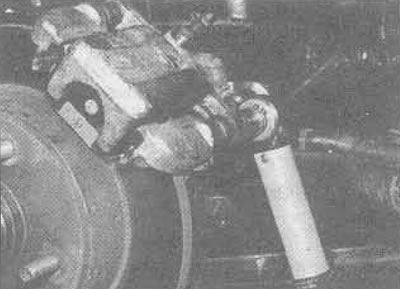
23.11. Tighten the caliper pin bolt
12. Connect the handbrake cable to the lever and bolt it to the caliper body, ensuring the pins are positioned correctly. Install the wheel.
13. Repeat the complete procedure on the opposite brake caliper assembly, lower the vehicle to the ground and tighten the wheel nuts to the torque specified in the Specifications.
14. Check the fluid level in the tank.
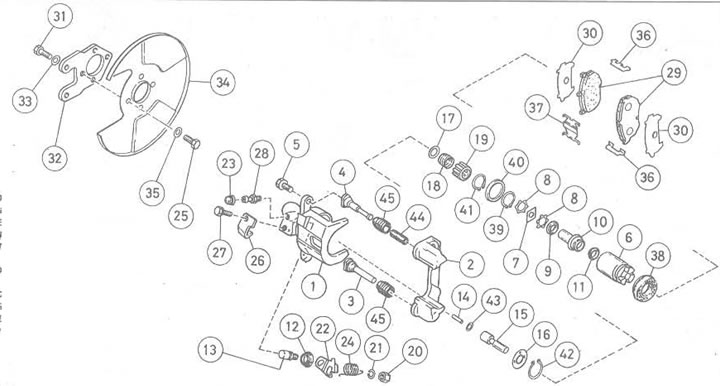
Figure 9.23. Rear brake caliper: 1. Caliper housing; 2. Suspension mounting of the caliper; 3. Rear guide pin; 4. Front guide pin; 5. Guide pin bolt; 6. Piston; 7. Embossed gasket; 8. Gasket; 9. Ball bearing; 10. Set nut; 11. Insulation of the cylinder; 12. Dust cap; 13. Cam; 14. Plunger; 15. Pusher; 16. Plate; 17. Spring socket; 18. Spring; 19. Spring cover; 20. Nut; 21. Grover; 22. Lever; 23. Dust cap; 24. Return spring; 25. Bolt; 26. Handbrake cable limiter; 27. Bolt; 28. Nipple; 29. Brake pads; 30. Gasket; 31. Bolt; 32. Steering knuckle connecting plate; 33. Laying; 34. Brake disc shield; 35. Laying; 36. Anti-rattle spring; 37. Retainer; 38. Dust seal; 39. Retaining ring "A"; 40. Piston seal; 41. Retaining ring "B"; 42. Retaining ring "C"; 43. O-ring; 44. Rubber bushing (where provided); 45. Rubber dust cap