


Table of contents: Direct acting steering (left side) ↓ Direct acting steering (right side)…↓ All models ↓
1. Apply the handbrake, engage 1st or reverse gear (manual transmission) or "R" (automatic transmission).
2. Remove the wheel cap and loosen the wheel nuts.
3. Raise the front of the car. Remove the wheel.
4. Remove the outer ball joint of the steering rod. Unscrew the ball joint lock nut.
5. The procedure now differs depending on the steering system used and the side being serviced.
Direct acting steering (left side)
6. Remove or loosen the clamps and pull the ball joint dust cap off the steering rod.
7. Mark the alignment of the rubber boot with the steering gear housing, remove or loosen the clamps and pull the boot inward over the housing until it comes off the steering shock absorber mount.
8. Turn the steering wheel to the right until it stops. Unscrew the steering rod and the inner ball joint. Remove the steering gear shock absorber suspension and the lock plate.
9. If necessary, replace the tie rod and inner ball joint assembly. Do not attempt to remove them further.
10. When assembling, thoroughly clean all parts and lubricate the threads of the inner ball joint and rack. Install the protective cover, dust cap and brackets. Lubricate the ball joint with the specified lubricant.
11. Install the steering shock absorber hanger onto the end of the rack, then install the new lock plate. Check that the location keys engage correctly with each other and with the rack (figure 10.32).
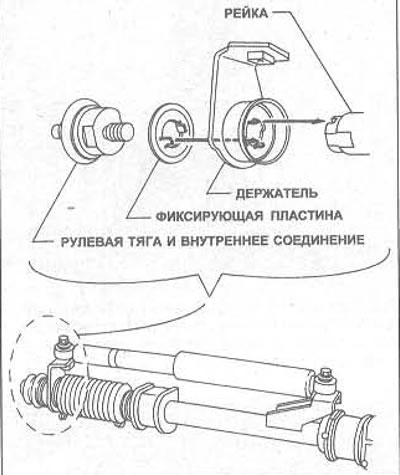
Figure 10.32 Correct installation of the lock plate and steering shock absorber hanger - direct acting steering, left side
12. Apply a few drops of locking compound to the threads, screw the steering rod and inner ball joint into the rack. Tighten them to the specified tightening torque Specification.
13. Lock the inner ball joint and tie rod by bending the two parts of the lock plate to opposite chamfers, then remove the burrs with a fine file.
14. Install the protective cover and (if any) ball joint dust cap, secure them with brackets as described in Chapter 27 of this Section.
Direct acting steering (right side) and power steering (both sides)
15. Disconnect the breather pipe (where is available). Remove or loosen the clamps and pull the protective cover off the steering rod.
16. Remove the lock plate, unscrew the steering rod and the inner ball joint.
17. Replace the tie rod and inner ball joint if the ball joint moves too hard. Do not attempt to disassemble them further. Replace the lock plate.
18. When assembling, thoroughly clean all parts and lubricate the threads of the inner ball joint and rack. Install the protective cover and brackets on the steering rod. Lubricate the ball joint with the specified lubricant.
19. Install a new lock plate onto the end of the rack. On turbocharged models, be sure to install a spacer between the end of the rack and the lock plate (figure 10.33).
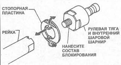
Figure 10.33 Correct installation of lock plate - direct acting steering, right side, power steering, both sides
20. Apply a few drops of locking compound to the threads, screw the inner ball joint and steering rod into the rack. Tighten them to the tightening torque specified in the Specification.
21. Lock the inner ball joint and tie rod by bending the two parts of the lock plate to opposite chamfers, then use a fine file to file down the burrs.
22. Install the protective cover, secure it with staples (see Chapter 27 of this Section).
All models
23. Install the outer ball joint of the steering rod and the wheel, lower the car to the ground, check the wheel alignment and steering angles (see Chapter 25 of this Section).