


Table of contents: Direct acting steering (left side) ↓ Direct acting steering (right side)…↓ All models ↓
1. Apply the handbrake, select reverse first (manual transmission) or position "P" (automatic transmission).
2. Remove the wheel trim (where necessary) and loosen the wheel nuts.
3. Jack up the front of the car and support it on axle stands. Remove the wheel.
4. Remove the outer ball joint of the steering rod as described in Chapter 25 of this Section. Carefully clean the steering rod, unscrew the ball joint lock nut.
5. The procedure now differs depending on the steering system used and the side being serviced.
Direct acting steering (left side)
6. Remove or loosen the clamps, pull the ball joint dust cap along the steering rod.
7. Use paint to mark the connection of the rubber protective boot to the steering gear housing, then remove or loosen the clamps, pull the protective boot inward along the housing until it is free of the steering gear shock absorber suspension.
8. Turn the steering wheel fully to the right and disconnect the inner ball joint and tie rod from the steering rack (see Chapter 26 of this Section).
9. Pull off the protective cover from the gear housing, check its condition. Similarly, remove and check the dust cap. Replace them if they are worn, damaged or leaking. Replace the brackets.
10. When assembling, clean the gear housing and steering rod. Install the protective cover and brackets on the gear housing, install the steering rod and the inner ball joint on the rack (see Chapter 26 of this Section).
11. Apply suitable sealant to the mating surfaces of the protective boot on the gear housing, place the protective boot on the housing and on the steering shock absorber hanger; align the marks made during removal. Pull the dust cap back into place, secure the protective cover and cover, installing new brackets.
12. If the clips of the protective cover are made of wire with a loop at each end, they are installed as follows: Wrap the clip twice around the groove of the protective cover with the ends at the back (when the steering gear is installed in the car). Insert a screwdriver through the hinges and twist them together 4-4.5 turns. Do not overtighten the brackets. Bend the curved end so that it does not touch other components.
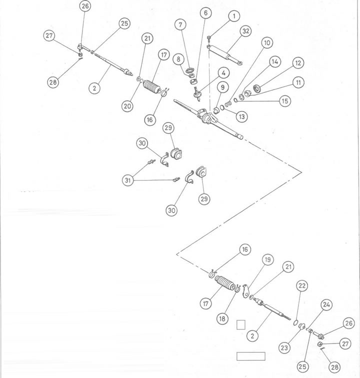
Figure 10.34. Direct acting steering elements: 1. Steering damper mounting bolt Steering rod and inner ball joint assembly Steering gear housing; 2. Assembly of the gear; 3. Steering rack; 4. Gear nut; 5. Lock nut; 6. Oil seal; 7. Guide shoe; 8. Spring; 9. Regulator; 10. Lock nut; 11. Spring seat; 12. Washer; 13. Washer; 14. Protective coating bracket; 15. Protective coating; 16. Protective coating bracket; 17. Steering shock absorber suspension; 18. Protective coating bracket; 19. Locking plate; 20. Dust cover bracket; 21. Dust cap; 22. Dust cover bracket; 23. Outer lock nut of the ball joint of the steering rod; 24. Outer ball joint of steering rod; 25. Outer lock nut of the ball joint of the steering rod; 26. Pin; 27. Steering gear support cushion; 28. Steering gear support clamp; 29. Clamp bolt; 30. Steering damper
Direct acting steering (right side) and power steering (both sides)
[The source is published on the portal www.NISSANBOOK.ru]
13. Use paint to mark the connection of the rubber protective cover with the steering gear housing, disconnect the breather pipe (if any), then remove or loosen the clamps, pull the protective cover off the steering rod.
14. Check the condition of the protective cover, replace it if there are signs of damage or leakage. Replace the brackets.
15. When assembling, clean the gear housing and steering rod. Do not forget to lubricate the inner ball joint.
16. Apply suitable sealant to the mating surfaces of the protective boot on the gear housing (both systems) and steering rod (power steering). Pull the protective cover back into place, aligning the marks made during removal.
All models
17. Install the outer ball joint of the steering rod and the wheel, lower the car to the ground, check the wheel alignment and steering angles (see Chapter 25 of this Section).