Examination
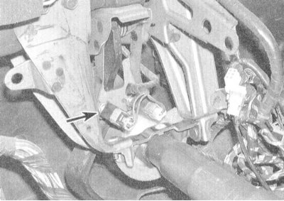
1. The sensor-switch is located on the left on the bracket near the top of the foot brake pedal, - the sensor-switch of the speed control system is placed on the right. The sensor-switch ensures the inclusion of brake lights in the assemblies of the rear combined lamps when the foot brake pedal is depressed.
2. Visually verify that the brake lights are working properly when the pedal is depressed and that they turn off when the pedal is released.
3. If the brake lights do not turn on, make sure the pedal adjustments are correct (see Section Foot brake pedal adjustment), then adjust the sensor-switch itself.
4. The sensor-switch is attached to the support bracket with a lock nut. Loosen the locknut and rotate the sensor-switch so that the gap between the end face of its plunger and the pedal stop does not go beyond the range of 0.3 ÷ 1.0 mm (the plunger must be free). Tighten the lock nut and repeat the check for proper functioning of the sensor-switch.
5. If the adjustment of the position of the sensor-switch does not correct the situation, then there is a violation of the power supply to the sensor-switch, or a defect in the assembly itself. Using a voltmeter or a probe lamp, check for voltage at the sensor-switch connector. When the pedal is released, voltage should be present only on one of the connector terminals, when the pedal is depressed, on both. A defective sensor-switch must be replaced.
Replacement
1. Disconnect the electrical wiring from the sensor-switch.
2. Loosen the locknut and unscrew the sensor-switch from the support bracket.
3. Installation is carried out in the reverse order.
4. Adjust the foot brake pedal (see Section Foot brake pedal adjustment), then, if necessary, adjust the sensor-switch (see above).