2. Loosen the 4 pinch bolts on the rear cover (photo).
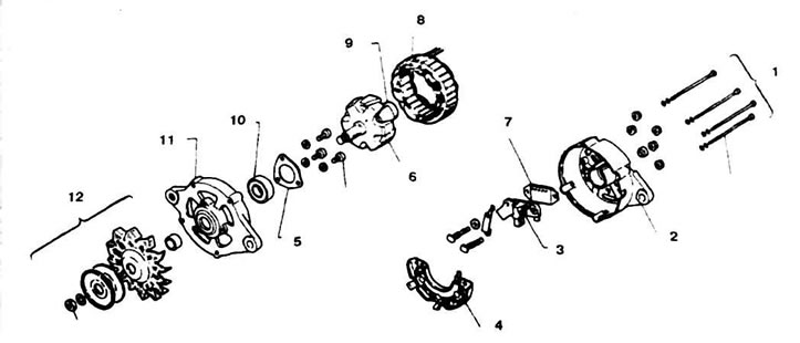
16.2 Generator parts (without rear dust cover)
1. Coupling bolt; 2. Back cover; 3. Brush holder; 4. Rectifier; 5. Front bearing housing; 6. Rotor; 7. Regulator; 8. Stator; 9. Rear bearing; 10. Front bearing; 11. Front cover; 12. Pulley
3. Remove the two screws and nut and remove the cover. With a light tap, separate the front cover with the rotor.
4. Remove the 5 nuts on the rear cover and remove the stator (photo).
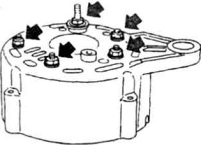
16.4 Stator nuts
5. Check the length of the brushes, replace if necessary. Before soldering, extend the brush by 11 mm and carefully solder the leads in the indicated places (photo) loop at the end of the wire (wrapping the wire 1 turn).
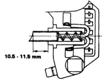
16.5a Arrangement of brushes before soldering
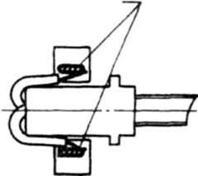
16.5b Places for soldering brushes
6. To replace the regulator, do the following (remove the regulator only if it is necessary to replace it).
- A). Disconnect the regulator from the rectifier by unsoldering the lead and removing the rivet (photo). It is recommended to unsolder the stator wires from the rectifier first.
- b). Disconnect the regulator from the brush holder, to do this, remove the solder and pull out the pins with pliers.
- V). When installing a new regulator, be careful (light blows) press the pins, solder all connections and rivet by installing a new rivet.
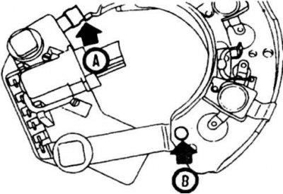
16.6 The regulator is attached to the rectifier by soldering (A) and rivet (IN)
7. Assemble and install the generator in reverse order.