


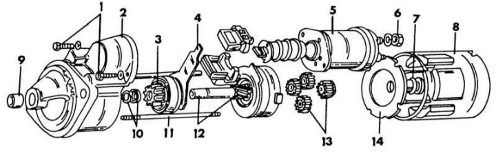
Wiring diagram of the front part of the starter with a reduction gear
1 - bolts, 6 Nm; 2 - front bearing shield; 3 - starter gear; 4 - power lever; 5 - traction relay; 6 - nut, 7 Nm; 7 - bushing; 8 - starter housing; 9 - bushing; 10 - flange ring and retaining ring; 11 - through bolts; 12 - drive shaft; 13 - downshift; 14 - intermediate bearing shield
The illustration below shows the parts installed on the back of the starter, together with the anchor. The direct drive starter has a conventional design and is easy to disassemble.
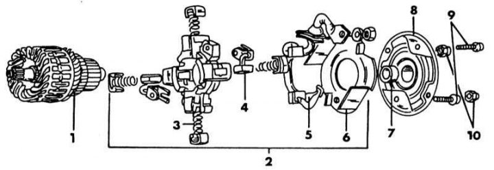
Elements on the back of the starter
1 - anchor; 2 - brush mechanism; 3 - brush spring; 4 - minus brush; 5 - positive brush; 6 - insulating insert; 7 - shaft sleeve; 8 - cover from the collector side; 9 - bolt, 3.0 Nm; 10 - nut, 6 Nm
1. Loosen the bolts on the front side of the solenoid relay and disconnect the engagement lever to remove the relay.
2. Loosen the bolts and nuts on the back of the starter and remove the cover on the collector side. Remove the starter housing from the armature and the front bearing shield.
3. Remove the brushes from their holders and remove the remaining parts from the back of the starter. Remember the exact location of the individual components (illustration).
4. Remove the remaining parts, following the instructions illustration.
5. The brushes are soldered to the pole coils and can only be replaced by replacing the entire pole coil housing.
[The text is published on the website: NissanBook.ru]