Disassembly
Carry out the following work, guided by the illustration below. The illustration shows a Bosch generator, which is installed on vehicles with a 2.0 liter engine. A Magnetti-Marelli generator is installed on the carburetor engine. The main difference lies in the absence of a mounting plate, since the bearing is pressed directly into the end shield. This should be taken into account in the following description.
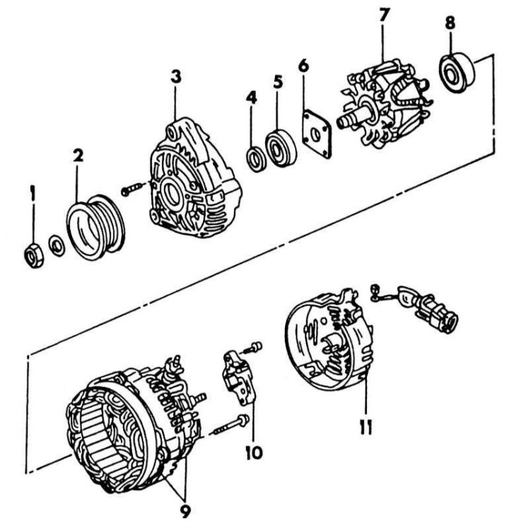
Bosch Generator Wiring Diagram
1 - nut, 45-55 Nm; 2 - belt pulley; 3 - drive bearing shield; 4 - remote washer; 5 - ball bearing; 6 - mounting plate; 7 - anchor; 8 - contact ring bearing; 9 - stator, regulator and diodes; 10 - brush holder; 11 - back cover
1. Unscrew the nut from the armature shaft and remove the belt pulley from the shaft, as well as the fan and spacer (if available). The shaft, when loosened, can be held with an old V-belt, superimposed on the belt pulley, and clamped in a vice. A 2- or 3-jaw puller can be used to remove the belt pulley. It should be remembered that the belt pulley is defined for this engine.
2. Remove the key from the shaft.
3. Unscrew and take out the regulator together with the brush holder.
4. Mark the drive bearing shield and housing in opposite positions and remove both pinch bolts from the housing. Separate the rear bearing cover from the front. To do this, you can lightly tap on the front cover with a polymer hammer.
5. Place the bearing shield and anchor under the press and remove the anchor with a three-jaw puller. When pressing out, the bolts of the mounting plate may break out. Therefore, make sure that the three arms of the puller are installed under the mounting base plate, and not just under the bearing shield. If you need to remove the bearing from the shield, loosen the bolts on the inside and press the bearing out.
6. Push the bearing away from the end of the armature slip rings. If a puller is used for this, it should be installed under the inner race of the bearing.
7. Unsolder the diode board from the stator. To do this, take the wires at the soldering points between the stator and the soldering iron with tongs, which will serve to remove heat. Diodes should not overheat.
8. Rectifier diodes should be removed with the right tools and experience.
9. If you have experience, check the details as follows.
Checking brushes and brush holder
1. Check up reliability of contact of brushes with contact rings.
2. Check the mobility of the brushes in the brush holders, if necessary, clean the brush holders with "Tri".
3. If the protruding part of the brush is worn to the boundary line, it is necessary to solder new brushes. On a Bosch generator, the protruding length should be 10 mm; on a Magnetti-Marelli 5 mm generator. Use a ruler to measure.
Anchor check
If the slip rings are dirty or greasy, they should be wiped with a cloth soaked in the product "Tri". Existing grooves can be polished with very fine sandpaper.
1. To check the insulation, attach the ohmmeter probes to the armature core and slip rings. If the reading is not equal to infinity, the armature must be replaced. Attach the probes to the anchor as shown in the illustration below.
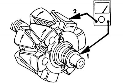
Connection method when checking the armature winding for a short to ground. One ohmmeter probe (1) attach to the slip ring, another probe (2) to the iron core. Check the other slip ring in the same way.
2. To check the armature winding for current flow, attach both probes to the slip rings. The device should show some resistance. If the ohmmeter shows infinity, then there is a break, if vice versa, then a short circuit. An ohmmeter is connected as shown in the illustration below. With both faults, the armature should be replaced, but it is better to install a new generator, as repairs will cost more in the end.
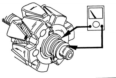
Checking the armature for the passage of current. Connect both ohmmeter probes to both contact rings.
Stator check
In case of a short circuit, the cause can be detected by the strong heating of the damaged area. Otherwise, connect one ohmmeter probe to the stator core and the other probe in turn to the three stator wires, as shown in the illustration below.
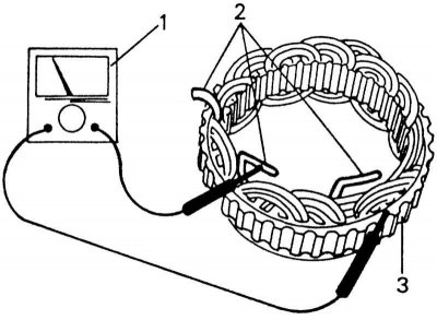
Checking the stator for a short to ground. Apply an ohmmeter in order (1) between three wires (2) and stator core (3).
The device should show infinity. To test the stator for current flow, connect the three stator cables to each other in pairs in order. If the meter shows nothing, no current is flowing. When doing this, apply the probes as shown in the illustration below.
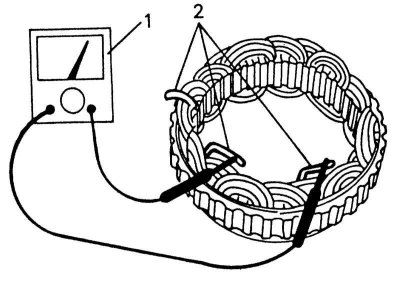
Checking the stator for current flow. Connect ohmmeter (1) in order with three cables (2). In this case, every two cables are checked together.
Diode test
An accurate test of the diodes for the forward voltage and determination of the locking current is only possible with a special device, and this test must be carried out in the workshop. A quick check can be made by connecting in order a powered ohmmeter between each diode and the diode board. Follow the readings. They must be either small or large. Reverse the polarity of the ohmmeter. Resistances that were small should become large, high resistances should become small.
Assembly
On illustrations the wiring diagram of the generator is shown, it should be used as a guide during assembly.
1. Assemble the drive bearing shield. To do this, press the bearing with the micro-notched side towards the rotor. On the Bosch generator, a washer must be installed under it. Place mounting plate and fasten with screws (Bosch only).
2. Install the anchor in the bearing shield. At the same time, position the shield well and press the anchor.
3. If it was necessary to solder the wires, they should be soldered in place. When doing this, use tweezers to remove heat so that the diodes do not overheat.
4. Check the inside of the stator and set aside any poorly routed wires so that they do not touch the armature.
5. Insert a small wire through the hole in the brush bearing cap to lift the brushes from the rings when the cap is installed. Slide the slip ring bearing shield onto the stator and drive bearing shield, making sure that the brushes are lifted above the rings by the inserted wire (see illustration below). Since the position of the brushes is not visible well, for this work you need to be patient. When the slip ring bearing shield sits, remove the wire. Screw on the slip ring bearing shield.
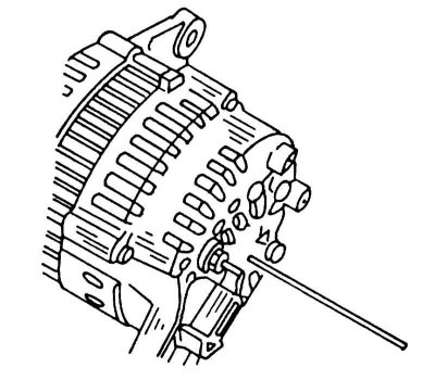
Insert a piece of wire into the alternator to lift the brushes before installing the cover.
6. Put on the spacer ring and fan (Magnetti-Marelli) on the armature shaft and put on the belt pulley. Tighten the nut to 45 - 55 Nm on a Bosch alternator or 70 to 90 Nm on a Magnetti-Marelli. To do this, the belt pulley can be clamped in a vice with soft metal jaws.