


Table of contents: Brushes ↓ Collector ↓ Pole coils ↓ Anchor ↓ Bearings ↓ Starter drive ↓ Traction relay ↓
Brushes
The brushes should be 5 mm long (with reduction gear) or 3.5 mm (direct drive). You can use a caliper to measure the brushes.
1. Check that the brushes move easily in the guides. If necessary, wipe the sides of the brushes with a rag soaked in gasoline or process them with a file. If necessary, replace the brushes.
2. Check the tension of the brush springs with a dynamometer, which is installed at a right angle to the spring. The result should correspond to the value in Specifications at the beginning of the Chapter.
Collector
A good collector should have a smooth surface without any pits or burnt areas.
1. Wipe the commutator with a rag soaked in gasoline while turning the starter. If necessary, it can be processed with sandpaper (with grain 500 - 600), as shown in the illustration below. To treat a heavily worn manifold, it can be machined.
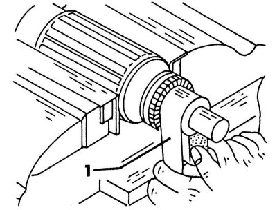
Clean the commutator with a strip of sandpaper (1). Clamp the anchor in various positions in a vice to clean the entire circumference.
2. The diameter of the manifold should first be measured with a caliper. If the measured (see illustration below) the diameter is already approaching the minimum permissible value of 28.8 mm, the collector should be replaced. The anchor for turning is clamped on a lathe, and when rotating at high speeds, a layer of metal is removed. Remove only the required amount of material.
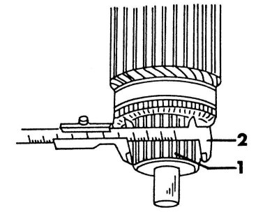
Measuring the diameter of the manifold (1) using a caliper (2).
3. Finally, saw the gaps between the collector segments to a depth of 0.5 - 0.8 mm. The hacksaw blade should be inserted horizontally into the gaps to cut along the entire length, i.e. do not skew the blade. Then polish the collector with fine sandpaper to create a shine. The most common faults in the collector are caused by a short circuit in the anchor (burnt collector turns), otherwise it should work for a long time.
Pole coils
1. The best way to check the pole coils is with an ohmmeter, which is connected between the positive terminal of the pole coil and the starter housing, as shown in the illustration below. The illustration shows an ohmmeter with an internal current source. An ohmmeter of another design should first be connected to the battery. This check checks whether the pole coils are shorted to ground. If the ohmmeter shows any value, the starter housing with the pole coils must be replaced.
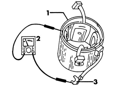
Check the insulation between the starter housing (1) and the positive terminal of the pole coil (3). Use an ohmmeter (2) to check.
2. The next test involves connecting an ohmmeter between the two brush contacts as shown in the illustration below. This test checks whether current flows between the brushes. If there is no reading, the starter housing should be replaced.
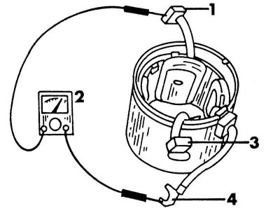
Checking the flow of current between the positive terminal of the pole coil and the positive brush
1 - positive brush; 2 - ohmmeter; 3 - positive brush; 4 - positive terminal
Anchor
To check the anchor winding, you need a special device, the so-called buzzer. If you don't have this device, you can check the old anchor by temporarily replacing it with a new one. Never try to straighten a bent anchor or process it, i.e. grind it down or remove burrs.
Bearings
Badly damaged bearings with lateral play must be replaced. The best way to do this is to measure the outer diameter of the armature shaft and the inner diameter of the bearing bore. If the difference between the two dimensions is more than 0.2 mm, press out the old bushing, soak the new bushing in clean engine oil for 30 minutes and press it into the bearing shield. Then turn the bushing until the shaft has a clearance of 0.03 - 0.10 mm.
Starter drive
Check that the starter pinion teeth are in good condition. The pinion should move easily on the armature shaft toothed connection. There should be free play only in one direction, in the other direction the pinion should lock. If necessary, replace the entire drive. In this case, also check the starter ring gear for damage.
Traction relay
The traction relay cannot be repaired. To check the traction relay coils, connect a 2-volt battery to the "S" and "M" terminals on the relay. The relay plunger should move. Repeat the same test, but this time connect the battery to the "M" terminal and the housing. The plunger should move and hold when the wire is connected to the "M" terminal. Illustration 7. m shows where the terminals are on the relay.
Source is available on the resource: Nissanbook.ru