


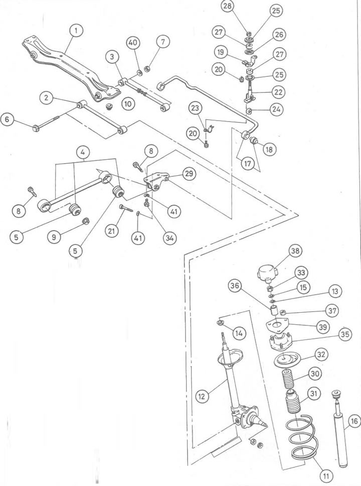
Figure 10.22. Rear suspension assembly view: 1. Suspension crossbar; 2. Front cross balancer; 3. Back (adjustable) cross balancer; 4. Assembly of the longitudinal balancer; 5. Rubber bushing; 6. Cross-beam pivot bolt; 7. Nut; 8. Longitudinal balancer mounting bolts; 9. Front longitudinal balancer mounting bolt nut; 10. Crossmember mounting nut; 11. Coil spring; 12. Assembly of the suspension strut; 13. Washer; 14. Pressure nut of the strut packing gland; 15. Spring washer; 16. Replacement cartridge type kit; 17. Anti-roll bar; 18. Rubber bushing; 19. Upper clamp of the rocker arm; 20. Clamp bolt; 21. Bolt; 22. Backstage; 23. Anti-roll bar clamp; 24. Rubber bushing; 25. Plate washer; 26. Plate washer; 27. Rubber bushing; 28. Self-locking nut; 29. Fastening the base of the suspension strut; 30. Rubber recoil buffer; 31. Dust cap; 32. Upper spring stop; 33. Piston rod nut; 34. Bolt; 35. Upper rack mount; 36. Gasket; 37. Upper strut mount nut; 38. Upper strut mount cover; 39. Gasket; 40. Washer; 41. Spring washer
1. First, from inside the car, access the upper suspension strut mounting nuts.
2. Note that on Sedan models it may be easier to access the upper strut mount nuts from inside the luggage compartment (photo). However, it is recommended to proceed as follows.
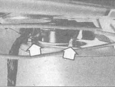
14.2A. On Sedan models there are two nuts (marked with arrows) the upper rear pillar mount can be removed from the trunk...
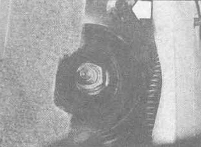
14.2V.... but the front nut (marked with an arrow) can only be reached from above
3. Working as described in the relevant Chapters Section 11, remove the rear seat base and pads, unfasten the top covers, unscrew the speakers (where are there), then release the shelf mounting brackets and remove the shelf.
4. On Hatchback models, remove the rear seat base, carefully remove the speaker grille (or tray), then remove the rear seat side pads (see Section 11).
5. On vehicles with non-adjustable suspension, remove the cover from the top of the suspension strut (photo).
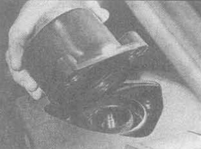
14.5. Removing the upper rear suspension cover - Hatchback model
6. On vehicles with adjustable suspension, first disconnect the strut actuator wiring harness, then remove the strut top cover from the strut piston rod by squeezing the top cover together at the points shown in Figure 10.23.
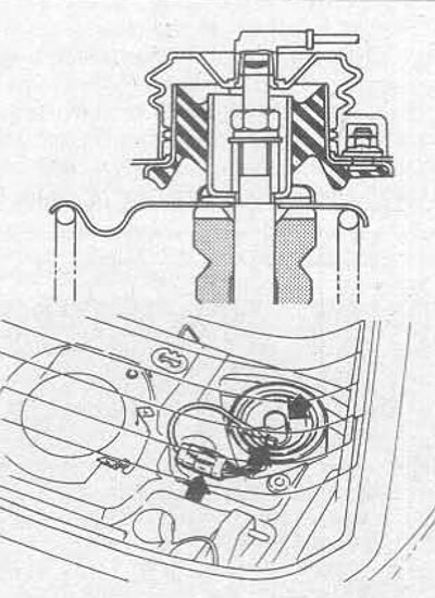
Figure 10.23. Rear upper mounting parts (adjustable) suspension struts
7. On all vehicles, loosen the three upper strut mount nuts 1-2 turns.
8. Raise the rear of the vehicle, remove the wheel and brake drum or disc.
The publication is reprinted from this resource NissanBook
9. On vehicles with rear drum brakes, disconnect the handbrake cable, remove the spring clamp securing the brake system high-pressure line pipe and the pipe to the suspension strut. Unscrew the drum brake shield from the lower end of the suspension strut. It is not necessary to disconnect the hydraulic system components.
10. On vehicles with rear disc brakes, if required, the disc shield and caliper mounting plate can be removed from the lower end of the suspension strut.
11. On all vehicles, loosen both longitudinal balancer mounting bolts, remove the rear mounting bolt, and move the balancer down away from the suspension strut.
12. Unscrew the suspension from the base of the suspension strut.
13. Loosen both cross lock nuts of the balance arm pivot bolt, remove the outer pivot bolt, move both balance arms down away from the suspension strut.
14. Unscrew the three nuts of the upper suspension strut mount, remove the strut from under the rear wing; remove the gasket (where is available).
15. Installation is carried out in reverse order.
16. Adjust the rear wheel alignment.