


Removing
1. Loosen the wheel nuts. Jack up the front of the car and place it on jack stands. Remove the front wheels.
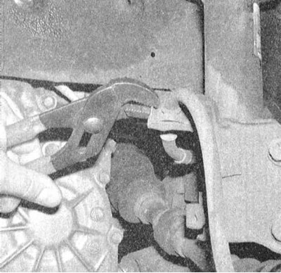
2. Release the flexible brake hose from the bracket on the suspension strut.
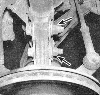
3. Give two nuts and by means of a hammer and a punch knock out two bolts of fastening of a rack to a rotary fist.
4. Separate the rack from the steering knuckle assembly, - try not to allow excessive pulling of the inner CV joint of the drive shaft, in order to avoid damage to the brake hose, do not allow the knuckle to fall out excessively.
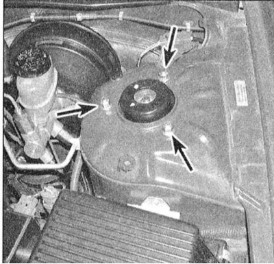
5. Holding a rack, give three top nuts of its fastening on a basic ledge of a mudguard of a wheel arch.
Note. When giving the last nut, hold the rack with your free hand. Remove the rack assembly through the wheel arch.
Examination
1. Carefully inspect the outside of the strut housing for signs of hydraulic fluid leaks, cracks, dents, or other mechanical defects that require appropriate refurbishment or replacement of the assembly.
2. Check the coils of the post spring for chips, cracks, or other damage to the protective coating that could lead to bar corrosion. Estimate a condition of a rubber pillow of a saddle of a spring.
3. If necessary, disassemble the rack (see Section Shock absorber/coil spring replacement strut assembly).
Installation
1. Get the rack assembly through the wheel arch to its regular place. Carefully insert the mounting studs into the holes in the top support. Screw the nuts onto the studs immediately, hand-tight for the time being.
Note. Due to the considerable weight of the shock absorber assembly, it would be wise to enlist the help of an assistant.
2. Fill a rotary fist in a rack flange and pass two fixing bolts into the sockets. Fit new nuts and tighten them to the required torque.
3. Fix a brake hose in an arm on a rack, snap on a clamp.
4. Install the wheels, lower the vehicle to the ground and tighten the wheel nuts to the required torque (see chapter Settings and ongoing maintenance).
5. Torque tighten the top rack mounting nuts.