Front suspension design
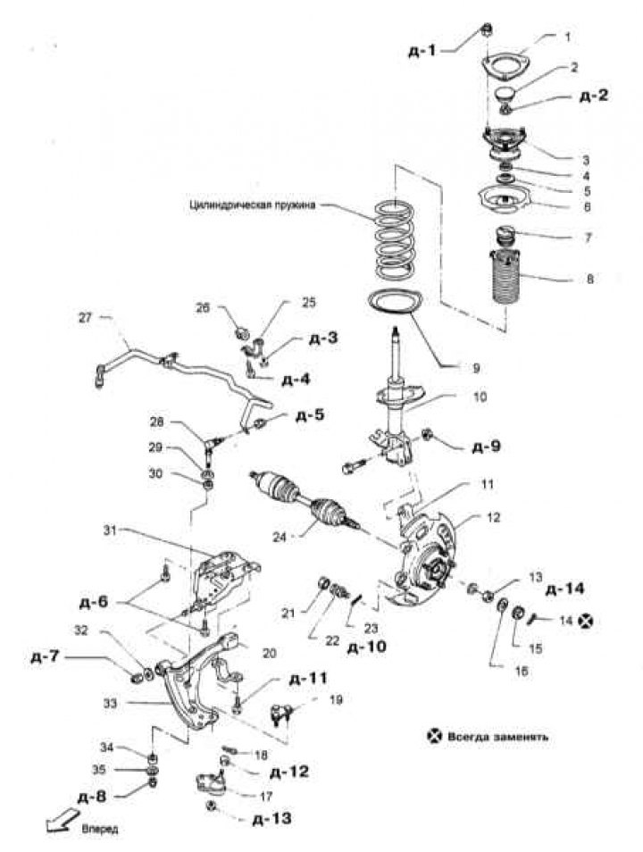
1 - Gasket; 2 - Cover; 3 - Cushion of the upper support; 4 - Thrust bearing; 5 - Bellow; 6 - Upper spring plate; 7 - Rubber damper; 8 - Protective cover; 9 - Rubber cushion; 10 - shock absorber; 11 - Swivel fist; 12 - Brake shield; 13 - Wheel bearing locknut; 14 - Cotter pin; 15 - Protective cap; 16 - Rubber gasket; 17 - Assembling the ball joint; 18 - Cotter pin; 19 - Bolt; 20 - Bushing; 21 - Bolt head; 22 - Locking bolt; 23 - Cotter pin; 24 - Drive shaft; 25 - Clamp; 26 - Bushing; 27 - Bar stabilizer bar; 28 - Stabilizer bar; 29 - Washer; 30 - Bushing; 31 - Kerchief; 32 - Flat washer; 33 - Suspension control lever; 34 - Bushing; 35 - Washer
Front suspension and steering components
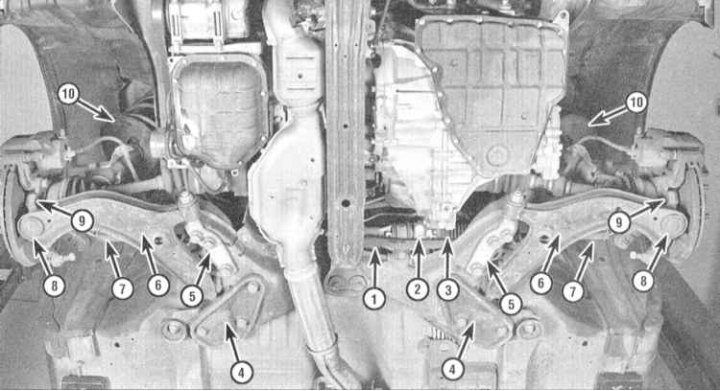
1 - Bar stabilizer bar; 2 - Rack and pinion assembly; 3 - Protective cover of the crankcase of the steering mechanism; 4 - Clamp for fastening the bushing of the suspension control lever; 5 - Finger of the bushing of the control lever; 6 - Suspension control lever; 7 - Tie rod end; 8 - Ball joint; 9 - Swivel fist; 10 - Rack Assembly
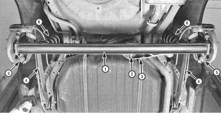
Rear Suspension Components (1993 and 1994 models issue)
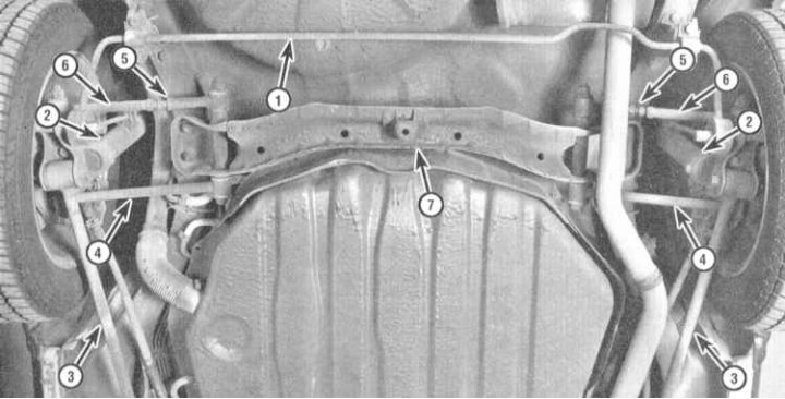
1 - Bar stabilizer bar; 2 - Rack assembly; 3 - Longitudinal suspension arm (radial rod); 4 - Front transverse arm; 5 - Wheel toe-in regulator; 6 - Rear transverse lever; 7 - Cross bar suspension
Rear suspension design for 1993 and 1994 models issue
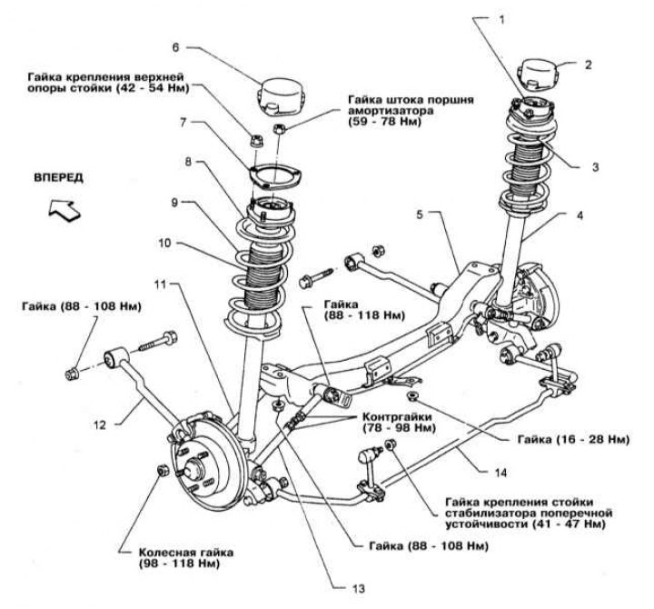
1 - Pillow of the upper support of the rack; 2 - Cover; 3 - Rubber damper; 4 - Telescopic shock absorber; 5 - Cross beam suspension; 6 - Cover; 7 - Gasket; 8 - Upper spring plate; 9 - Helical spring; 10 - Protective cover; 11 - Front transverse arm; 12 - Trailing arm (radial rod); 13 - Rear transverse arm; 14 - Bar stabilizer bar
Rear Suspension Components (models since 1995 issue.)
1 - Assembling the rear axle; 2 - Suspension control rod; 3 - Transverse jet rod; 4 - Longitudinal suspension arm; 5 - Telescopic shock absorber; 6 - Helical spring
The design of the rear suspension of models since 1995, no.
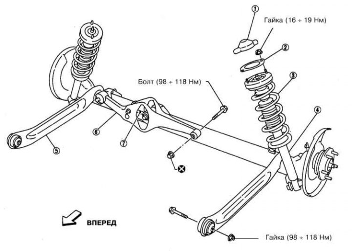
1 - Cover; 2 - Gasket; 3 - Helical spring; 4 - Telescopic shock absorber; 5 - Trailing arm; 6 - Transverse jet rod; 7 - Suspension control rod
Steering column design
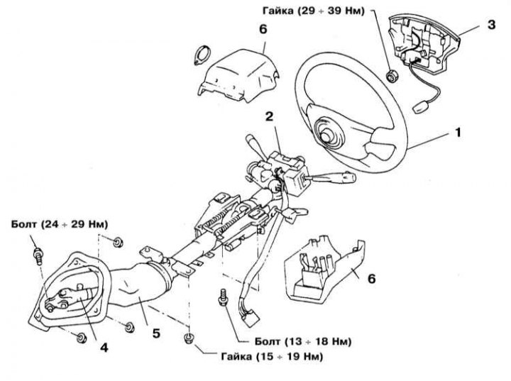
1 - Steering wheel; 2 - Combined steering column switches; 3 - Horn button; 4 - Cardan joint of the steering shaft; 5 - Protective cover; 6 - Upper and lower sections of the casing of the steering column
All models are equipped with MacPherson strut front suspension. The upper ends of the struts are fixed in the body supports at the rear of the wheel arch mudguards, the lower ends are attached to the upper parts of the steering knuckle assemblies. The steering knuckles are connected to the outer ends of the suspension control levers by means of ball bearings. Ball bearings are built into the control levers and, in case of wear, are replaced as an assembly with the latter. A front anti-roll bar is standard on all models. The stabilizer bar is attached to the car frame with a pair of clamps and is connected to the suspension control levers with the help of special racks.
In the rear suspension of 1993 and 1994 models. issue a rack-mount design was also used, which is based on assemblies of shock absorbers with coil springs complete with four transverse and two trailing arms. The upper ends of the rack assemblies are fixed on the car body, the lower ends are attached to the holders of the hub assemblies. Holders are fixed horizontally by means of longitudinal levers. The rear anti-roll bar is attached to the car body with two clamps and connected to the suspension struts by means of connecting rods.
On models since 1995, no. the rear suspension is organized by means of a continuous axle, hung out with the help of assemblies of telescopic shock absorbers with coil springs and unfastened by trailing arms and a transverse torque rod. By means of a transverse torque rod, freely rotating on the built-in control rod, the bridge is connected to the vehicle chassis.
All models are equipped with rack and pinion steering with hydraulic booster. The steering gear assembly is located behind the power unit at the bottom of the rear bulkhead of the engine compartment and is attached to the lower transverse beam. The rack and pinion is connected by means of a pair of transverse steering rods to the steering knuckles of the steered wheels of the vehicle. The inner ends of the steering rods are equipped with rubber protective covers, the condition and reliability of fastening of which should be checked periodically.
The power steering system consists of a steering pump driven by a belt drive and connecting lines. The fluid level in the steering pump reservoir should also be checked regularly (see chapter Settings and ongoing maintenance).
The steering wheel is mounted on the steering column and is connected to the rack and pinion by means of a steering shaft equipped with cardan joints. The wear of the components of the cardan joints, rack and pinion and tie rod ends, summing up, determines the amount of steering wheel play, which should not go beyond the permissible range.
Note. Steering wheel play can also be caused by loose steering components.
Often during the maintenance of suspension and steering components, one has to deal with hard-to-return fasteners. "sticking" fasteners due to the fact that they are constantly exposed to external influences, are in contact with water, dirt, soot and other substances that contribute to the development of corrosion. In order to facilitate the procedure for giving such "stuck" fasteners, it should be impregnated in advance with a copious amount of penetrating oil. Scouring exposed threaded parts of fasteners with a stiff wire brush also helps loosen rusted nuts. Sometimes, in especially severe cases, for letting go "stuck" bolts / nuts, you can use a drift. The punch rests against the edge of the slot of the nut / bolt head, then sharp blows are applied to its opposite end with a hammer. Make sure that the drift does not break, try not to damage the thread with inaccurate blows. Heating a non-retractable fastener and the surrounding surface of the component with a blowtorch or gas burner is also a fairly effective method, although the drafters of this Guide do not recommend resorting to this technology unless absolutely necessary due to its potential danger associated with the possibility of fire and the risk of burns. To increase the torque when releasing fasteners, various kinds of extensions, gates and pipe nozzles are used on them. However, remember that you should not use this kind of amplifying devices complete with equipped "ratchet" drive - the risk of failure of the ratchet mechanism is too great. Sometimes "ingrained" the fastener begins to give in after it is preliminarily slightly tightened clockwise. All fasteners, the release of which required the use of extraordinary measures during assembly, must be replaced!
Note. After giving away, carefully check the condition of the fastener and, if necessary, replace it with elements of the same size. When assembling, tighten the fasteners of the suspension and steering components strictly with the required force.
Attention! Never attempt to straighten deformed suspension and steering components - replace defective parts with new ones!
Since the maintenance procedures for the suspension components are performed under the vehicle, care should be taken in advance to raise the vehicle and fix it in a raised position (prepare a reliable jack and props).
Under no circumstances should you carry out any work under the vehicle, which has only been secured in the raised position with a jack!