


Note. If defects in the protective cover are detected, the condition of the corresponding CV joint should be carefully examined. Often, fully restored drive shaft assemblies can be purchased on an exchange basis, which greatly simplifies the situation and reduces time costs. Before starting to dismantle the components, conduct marketing, finding out the prices of the necessary spare parts. Compare them with the costs of purchasing restored assemblies.
In car accessory stores you can find protective covers for CV joints of a split design. Installation of such covers does not require dismantling the shaft from the car, which is, in principle, very convenient. However, the authors of this Guide still recommend removing the shafts to check the condition of the CV joints and fill them with fresh grease.
Remove the drive shaft (see section Removal and installation drive shafts).
Inner CV joint
Disassembly
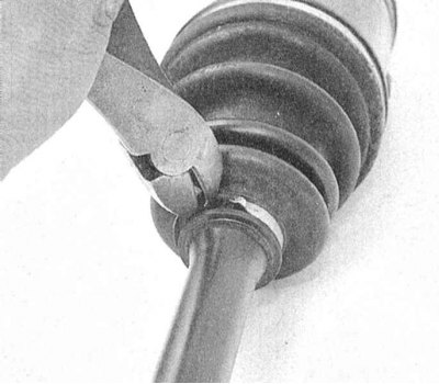
1. Remove the protective cover fastening bands and slide the latter along the shaft, providing unimpeded access to the joint.
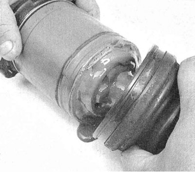
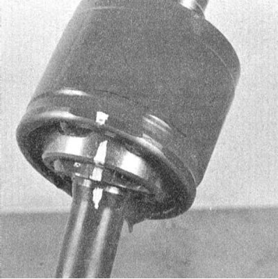
2. Mark the position of the inner race and the separator of the pivot assembly relative to the shaft.
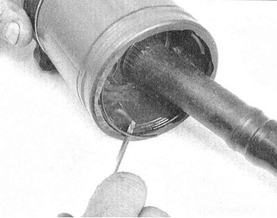
3. Using a small screwdriver, pry the inner retaining ring out of the hinge housing.
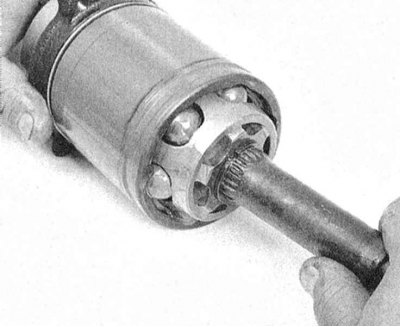
4. Remove the housing from the bearing assembly.
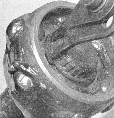
5. Using special pliers, remove the retaining ring from the mounting groove on the drive shaft journal.
6. Remove the inner bearing race from the shaft journal. If the splines are "sticking", soak the components with penetrating oil and carefully tap the assembly with a hammer through a brass drift.
7. Using a screwdriver and a wooden block, release the bearing balls from the separator, being careful not to damage the inner surfaces of the latter. Remove the separator.
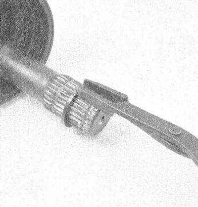
8. Remove the inner race retaining ring. Remove the joint protective cover from the shaft.
Checking the status
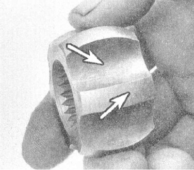
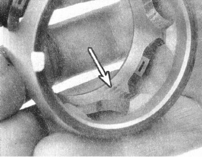
Wash the joint components in solvent, completely cleaning them from traces of old grease. Assess the condition of the inner race and separator for now.
 |
 |
Assembly
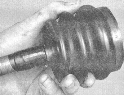
1. Wrap the splines on the shaft journal with a layer of tape, then place the protective cover of the joint on the shaft. Remove the tape and put a larger diameter bandage tape on the cover.
2. Place the bearing assembly separator on the shaft journal (with the smaller diameter side towards the central part of the shaft).
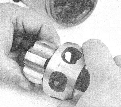
3. Snap the inner race retaining ring into place, then place the latter on the shaft journal, ensuring that the mounting marks applied during component dismantling are correctly aligned.
4. Secure the inner bearing race with a retaining ring, making sure that the latter is securely seated in the receiving groove on the shaft journal - the race should not move along the shaft.
5. Slide the separator onto the inner bearing race (again, check that the landing marks are aligned correctly) insert the bearing balls into the separator windows.
Note: To temporarily fix the balls in the assembly, first dip them in CV joint packing grease.
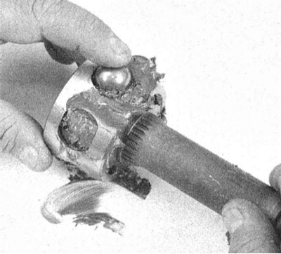
6. Pack the outer bearing race and the CV joint protective boot with grease (lubricant is usually supplied with a new cover). Fill the cavities of the separator and inner race with the same grease.
7. Insert the bearing from the side into the hinge housing and install the inner retaining ring.
Data copied from web resource www.nissanbook.ru
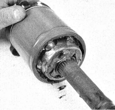
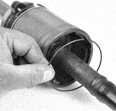
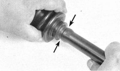
8. Remove excess grease from the groove under the boot seat on the outer race. Tuck the edge of the boot (from the smaller diameter side) into the mounting recess on the shaft body. Pull the other end of the cover onto the CV joint housing and move the assembly, eliminating any excess deformation of the rubber.
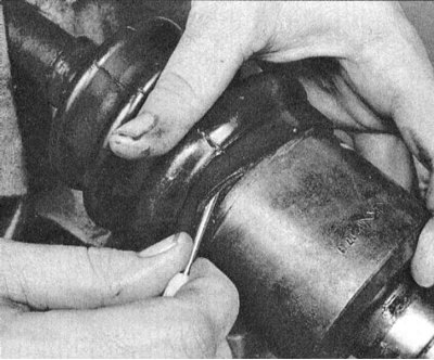
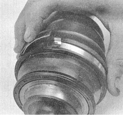
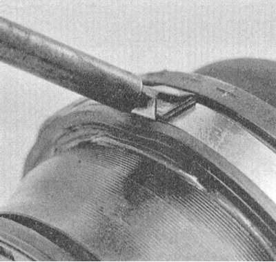
9. Adjust the seat length of the hinge protective cover. Using a blunt screwdriver, pry up the edge of the cover and equalize the pressure underneath it - try not to tear the cover.
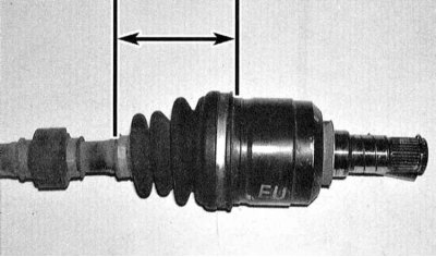
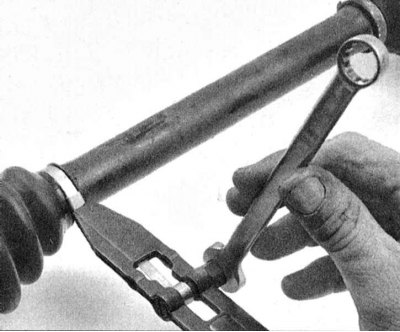
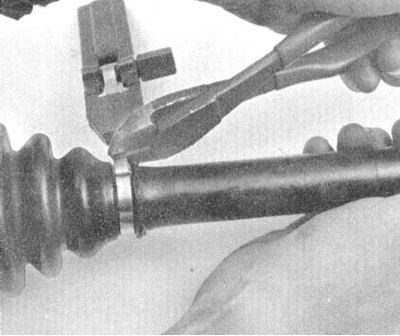
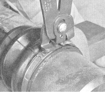
10. Secure the cover with bandage tapes.
11. Install a new snap ring onto the end of the inner CV joint assembly journal.
12. Install the drive shaft to the vehicle (see section Removal and installation drive shafts).
Outer CV joint
Removal
1. Release the protective cover fastening straps. Remove the cover from the hinge assembly.
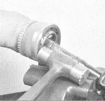
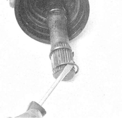
2. Clamp the shaft assembly in a vice with soft jaws and knock off the joint with a hammer with a brass striker. After knocking off the joint, remove the retaining ring of the inner bearing race.
 |
 |
3. Thoroughly wash the joint in solvent and dry it, if possible, using compressed air. The outer CV joint cannot be disassembled, so cleaning and packing it can take quite a lot of time.
Checking the status
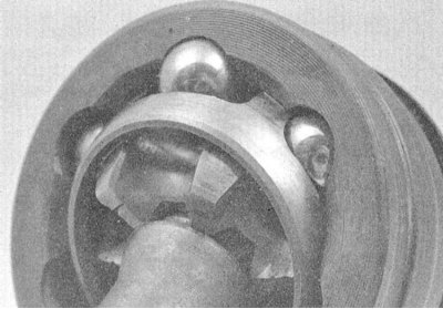
Bend the outer CV joint cover at an angle to the assembly axis so that access to the surfaces of the inner race, separator and bearing balls is opened. Assess the degree of wear and deformation of the components. The defective joint is subject to replacement.
Assembly
1. Pull the protective cover of the CV joint onto the shaft (it would be wise to wrap the splined shaft journal with a protective layer of tape beforehand). After placing the cover, remove the tape.
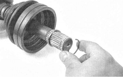
2. Install the retaining ring for fixing the inner bearing race.
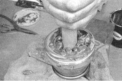
3. Tightly pack the cavities of the joint with fresh grease.
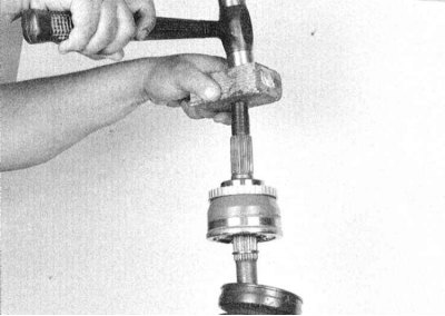
4. With the shaft resting vertically on the workbench surface, tap the hinge assembly onto it with a hammer through a wooden block.
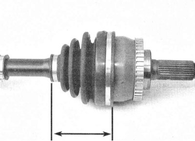
5. Place the protective cover in its regular place and stuff the remaining grease under it. Adjust the seat length of the cover. Equalize the pressure and secure the cover with new bandage tapes.
Both CV joints
Install the drive shaft in place (see section Removal and installation drive shafts).