


Table of contents: Removal ↓ Installation ↓
Drive shaft components
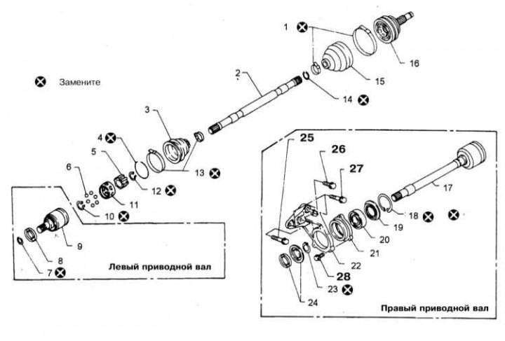
1 - Bandages for fastening protective covers; 2 - Drive shaft; 3 - Protective case; 4 - Retaining ring; 5 - Inner race of the inner CV joint; 6 - Balls; 7 - Retaining ring; 8 - Dust cover; 9 - Inner hinge housing; 10 - Retaining ring; 11 - Separator; 12 - Retaining ring; 13 - Cover fastening bandage; 14 - Retaining ring; 15 - Protective cover; 16 - Outer CV joint; 17 - Assembly of the outer sliding CV joint with the drive shaft; 18 - Retaining ring; 19 - Dust cover; 20 - Thrust bearing; 21 - Bearing support holder; 22 - Holder bracket; 23 - Retaining ring; 24 - Anthers; 25 - Bolt (30÷40 Nm); 26 - Bolt (25÷35 Nm); 27 - Bolt (43÷58 Nm); 28 - Bolt (13÷19 Nm)
Removal
1. The design of the drive shafts is shown in the illustration.
2. Remove the wheel cap.
3. Remove the cotter pin and remove the retaining cap and felt washer from the hub nut.
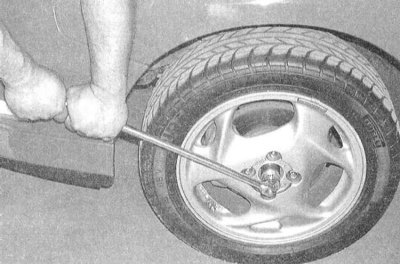
4. Using a long-handled socket wrench, loosen the hub nut, but do not loosen it completely yet.
(The article was obtained from the portal: NISSANBOOK)
Note: If the key head does not fit through the hole in the center of the wheel, remove the wheel and temporarily install the spare tire in its place.
5. Loosen the nuts of the corresponding front wheel. Jack up the car and place it on supports. Remove the wheel.
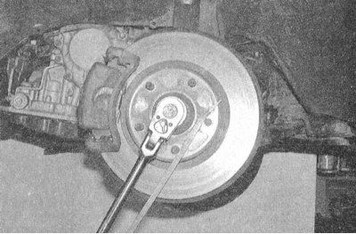
6. Loosen the hub nut and remove the washer. If the hub starts to turn while the nut is being loosened, wedge the tire iron between two wheel studs, resting its other end on the ground or a car body element.
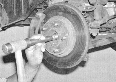
7. Use a hammer and brass drift to release the shaft journal from the hub assembly. If the components are stuck and the shaft does not budge, you will have to remove the brake disc (see Chapter Brake system) and use a 2-jaw puller.
8. Remove the crankcase guard and place a drain pan under the transmission assembly.
9. Remove the brake hose retainer from the suspension strut, then release the strut from the steering knuckle assembly (see Chapter Suspension and steering).
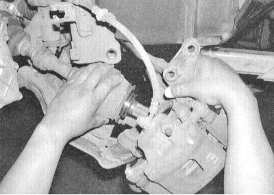
10. Pull the steering knuckle assembly outward and remove it from the drive shaft journal(try not to damage the brake hose).
Note: If the brake hose interferes with the removal of the steering knuckle, remove the brake caliper and, without disconnecting the hose, tie the assembly to the coils of the strut spring.
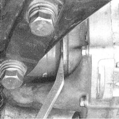
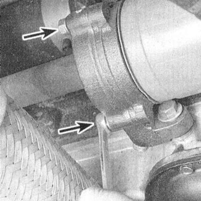
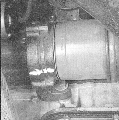
11. When removing the left shaft, use a pry bar to carefully release the inner CV joint journal from the transmission. The inner CV joint housing of the right shaft is threaded into the support bearing assembly. To release the assembly from the support bracket, unscrew the three bolts securing the latter to the bearing. Mark the position of the bearing in relation to the bracket and carefully remove the shaft assembly.
Note: When removing the left shaft on models equipped with AT, a situation may arise where it is not possible to release the inner joint from the transmission. In this case, first remove the right shaft, then insert a screwdriver through the side gears of the differential and knock out the left shaft from the inside.
 |
 |
12. Do not forget to replace the drive shaft seals in the transmission housing (see Chapter Transmission).
Installation
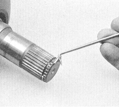
Installation is carried out in reverse order. Please note the following points:
- a) When installing the left shaft assembly, be sure to insert the new locking ring into the groove on the inner joint pin. Push the shaft sharply into the transmission, ensuring that the ring snaps into the counter groove in the differential side gear hub (there is no such ring on the right shaft - the assembly is secured by three bolts securing the support bearing bracket;
- b) When installing the right shaft, ensure that the bearing support retainer mounting bolts are tightened to the required torque;
- c) After installing the wheels, lower the vehicle to the ground and tighten the wheel nuts to the required torque (see Chapter Settings and ongoing maintenance);
- d) Make sure the hub nut is tightened to the correct torque, do not forget to install the felt washer and replace the cotter pin;
- e) Check the transmission oil level (models with manual transmission) or differential lubricant (models with AT), if necessary, make the appropriate adjustments (see Chapter Settings and ongoing maintenance).