


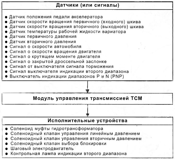
The task of the TCM control module is as follows:
- Receives signals from various switches and sensors.
- Determines the line pressure value, switching moment and locking.
- Sends output signals to the stepper motor and solenoids.
The control system is controlled by a variator. It determines the vehicle's operating conditions based on readings from various sensors, determines the optimal shift point, and reduces the force of impact during shifting and locking.
Block diagram of the control system
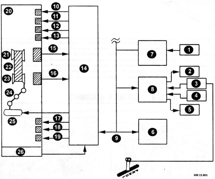
1 - wheel speed sensor; 2 — control lamp indicating the second range; 3 — second range indication switch; 4 — brake light switch; 5 — CVT mode indicator; 6 — Engine control module (ECM); 7 - actuator and electrical unit (control unit) ABS; 8 - combined amplifier for instrument panel and air conditioner; 9 — CAN bus; 10 — linear pressure control solenoid valve; 11 - secondary pressure control solenoid valve; 12 — torque converter clutch control solenoid valve; 13 — lock selection solenoid valve; 14 — transmission control module (TCM); 15 — secondary pulley speed sensor; 16 — primary pulley speed sensor; 17 — CVT working fluid temperature sensor; 18 — secondary pressure sensor; 19 — primary pressure sensor; 20 — continuously variable transmission (CVT); 21 - secondary pulley; 22 - belt; 23 - primary pulley; 24 — shift control rod; 25 - stepper motor; 26 — switch for indicating ranges P and N (PNP).
Location of electrical components of the variator
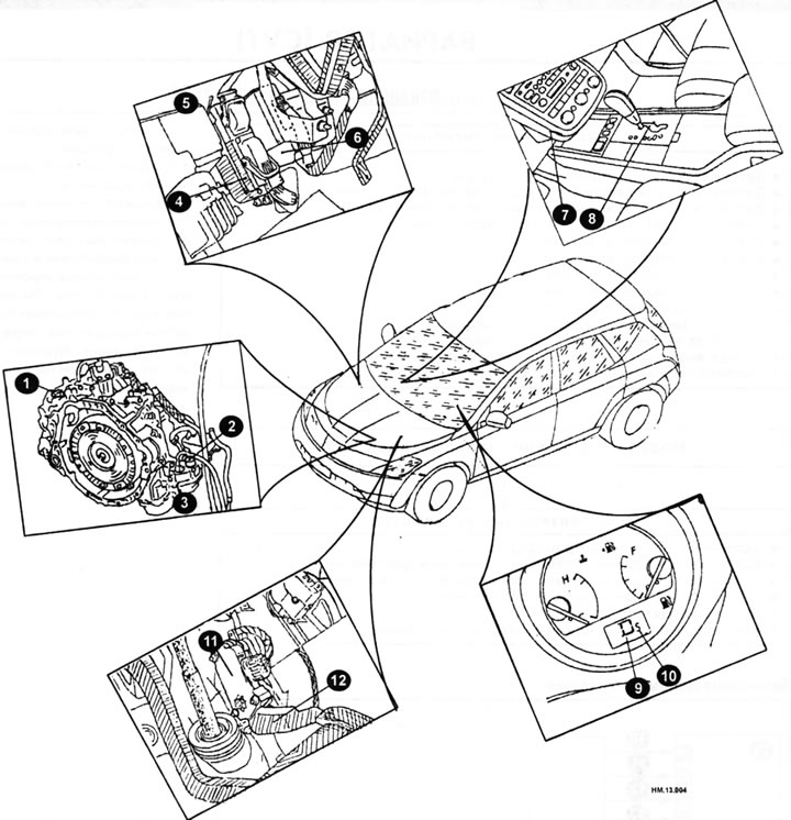
1 — secondary pulley speed sensor; 2 — CVT wiring harness plug; 3 - Control valves that include a PNP (Pulse Negative Pressure) indicator switch, a primary pulley speed sensor, a stepper motor, a secondary pressure control solenoid valve, a line pressure control solenoid valve, a torque converter clutch solenoid valve, a shift control valve, a secondary valve, a manual control valve, a torque converter clutch control valve, a lock-up select solenoid valve, a CVT fluid temperature sensor, a secondary pressure sensor, a primary pressure sensor, and 4 - Engine Control Module (ECM); 5 - behind the glove compartment; 6 — transmission control module TCM; 7 — variator control unit; 8 — second range indication switch; 9 — CVT mode indicator; 10 — second range control lamp; 11 — accelerator pedal position sensor; 12 — accelerator pedal.
(The source is published on the portal nissanbook.ru)