Table of contents: Wire color designations in…↓ Connector designations ↓ Designations on switches ↓ Wire connection designations ↓ Relay ↓
Wire color designations in electrical diagrams
| B | BR | SN | DG | G | GY | L | LG | OR | R | PU | R | SB | W | Y |
| Black | Brown | Tea | Dark green | Green | Grey | Blue | Light green | Orange | Pink | Purple | Red | Colorless | White | Yellow |
Two-color wires are designated by the "/" sign. In this case, the main color of the wire comes first, and the marking color comes second.
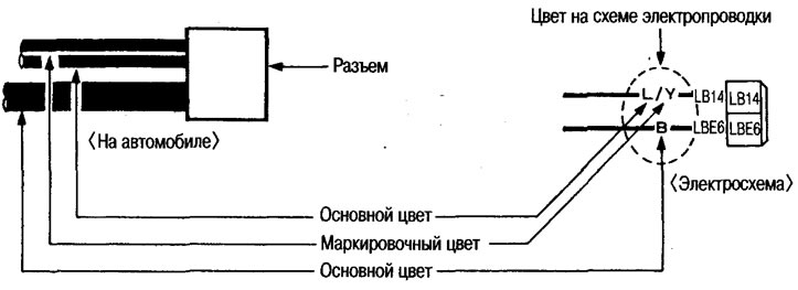
Connector designations
A schematic representation of a connector on an electrical diagram shows the number of contacts and the type of connector (male or female).
The material is taken from a web resource NISSANBOOK
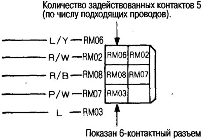
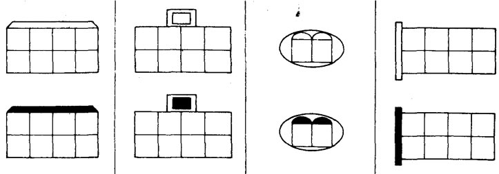
1. The number of contacts on the connector is determined by the number of cells on the schematic image of the connector. The number of contacts used in the connector is determined by the number of wires approaching it and the inscriptions in the cells.
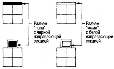
2. Male connectors are shown with a black guide section, female connectors are shown with a white guide section.
Examples of connector images
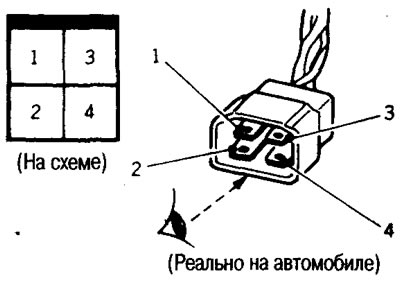
The numbering of contacts in the connector on the diagrams is indicated in the manner shown in the figure.
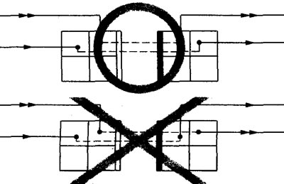
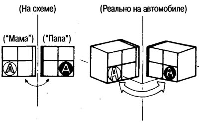
Matching the contacts in the connector
The correspondence of contacts in the connector ("male" - "female") on the diagrams is determined in the manner shown in the figures.
 |
 |
Designations on switches
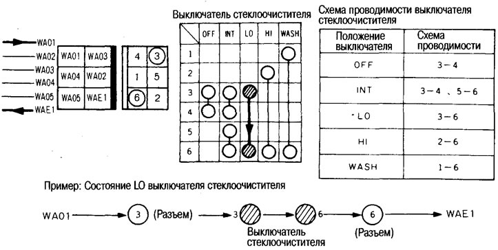
Wire connection designations
Wire connection locations are displayed in two ways:
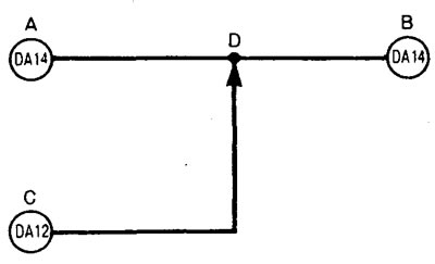
1. Connection

When there is a connection in the DA14 signal circuit between pins A and B, this is shown on the diagram as a black dot at junction D.
If there is a connection between contact C of the DA12 signal circuit and D, this is shown in the diagram by an arrow to connection point D.
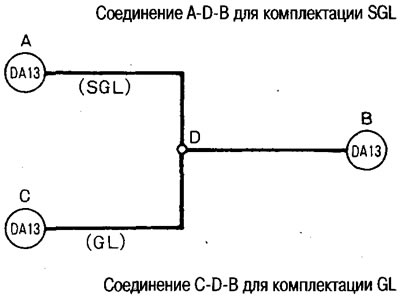
2. Connection depending on the configuration

If a connection exists for a certain vehicle configuration, this is indicated by a circle at the location of the possible connection.
For example, in the case of the SGL configuration there is an ADB connection, in the case of the GL configuration there is a CDB connection.
Relay
Normally open, normally closed and mixed type relays
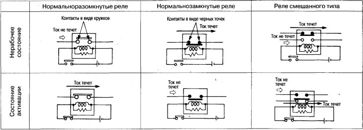
Note: The non-operating state is when no current flows through the relay magnetic coil, the activating state is when current flows.
Types and designation of relay contact groups
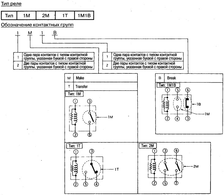
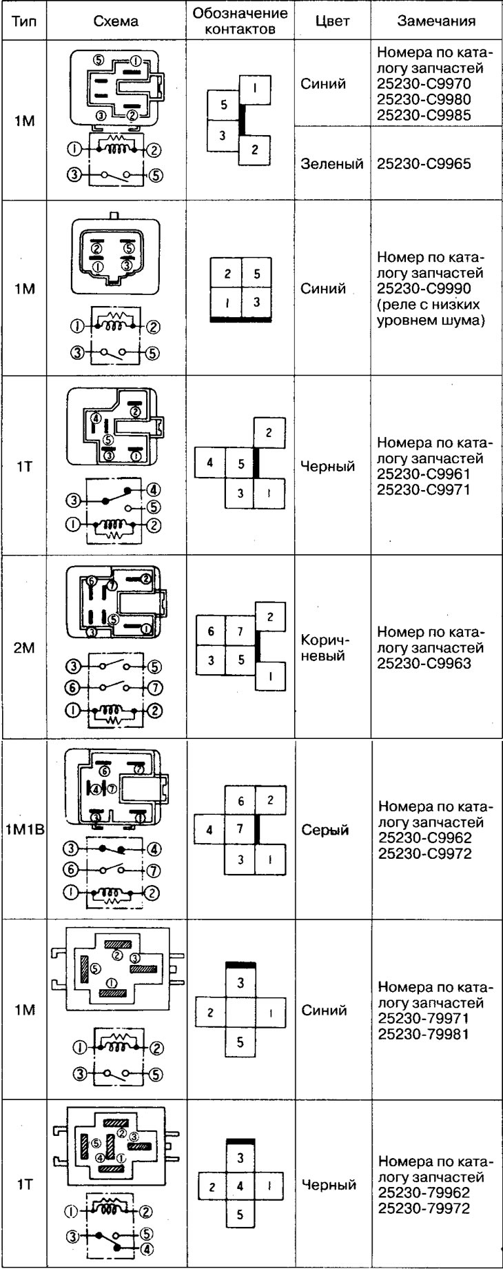
Relay designation
Note: The part numbers shown in the table below in the "Notes" column are interchangeable and vary by manufacturer.