


Table of contents: Cylinder block and crankcase ↓ Crankshaft and bearings ↓ Connecting rods ↓ Pistons and piston rings ↓ Flywheel ↓ Drive disk (automatic transmission) ↓ Sleeve ↓ Toothed belt drive and tensioning…↓ Oil pump ↓ Cylinder Head Components ↓ Seals and gaskets ↓
1. Thoroughly clean the engine and all parts, check the condition of each component. The units mentioned in the following Chapters should be given special attention and, where necessary, replaced or reconditioned.
2. Many engine part dimensions require measurement accuracy of tens of thousandths of a millimeter. Therefore, it is advisable to check your micrometer against a standard template.
3. When in doubt about whether a specific component should be replaced, consider not only the cost of the component, but also the time and effort it will take to replace the part if it subsequently fails.
Cylinder block and crankcase
4. Inspect the block casting for cracks, especially around bolt holes and between cylinders.
5. Check the cylinder bores for taper, ovality and scratches. Start checking from the top of the cylinder bore. You can determine bore wear before disassembly by oil consumption and blue smoke in the exhaust on a cold engine.
6. Use a bore gauge to measure the taper, comparing the data with the values in Specifications.
7. The engine can be rebuilt by boring out the cylinders in the block and using larger pistons (repair) size.
8. To eliminate minor wear of the cylinder bores, special oil rings can be used.
9. A good way to check the condition of the engine is to measure the compression (Chapter 25).
10. Some of the coolant passages in the cylinder block may be clogged. If so, drill a small hole in the center of the plug, screw a self-tapping screw into it and pull the plug out using it. Clean the hole and install a new plug using a socket of the appropriate size.
Crankshaft and bearings
11. Check the connecting rod pins and the surfaces of the main and connecting rod journals of the crankshaft for ovality and taper. If the dimensions of the working surface of the bearings are not within the tolerances given in Specifications, the necks need to be re-ground.
12. When the lower connecting rod head and pin are worn, a knocking noise is heard in the engine, especially noticeable when the engine is running at low speeds and there is low oil pressure.
13. When the main bearings wear out, a roar and vibration can be heard, and a drop in oil pressure can also be observed.
14. Crankshaft boring should be entrusted to a good specialist; it is better not to save on this.
15. Inspect the lower connecting rod head and main bearings. The bearings should be matte gray. Otherwise, the bearings must be replaced. We recommend replacing the bearings (regardless of their condition) during major repairs.
16. External (repair) dimensions are designed for use with a reground crankshaft. Bearings are actually slightly larger than the external dimension, since working clearances were allowed during their manufacture.
17. The sizes of the main and connecting rod bearings can be determined by the marking on the end of the housing. Standard bearing sizes are marked STD or.00, repair bearing sizes are marked - 0.020 u/s (photo).
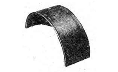
18.17 Bearing shell marking
Connecting rods
18. Visually check the connecting rods for bending.
19. The piston pin is fixedly seated in the upper head of the connecting rod.
Pistons and piston rings
20. If the engine cylinders are bored out, it is necessary to install new pistons of a larger size with rings and piston pins. The marking locations of the connecting rods and pistons are shown in Figure 1.34.
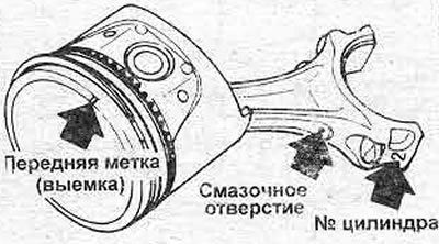
Figure 1.34. Installing the piston-connecting rod assembly
21. Removal and installation of piston rings are described in Chapter 9.
Flywheel
22. Check the clutch surface on the flywheel. If there is a large wear, the surface must be re-ground.
23. A large number of microcracks on the flywheel surface due to overheating caused by clutch slippage or driving with the clutch pedal not fully depressed.
24. Check the teeth of the flywheel starter ring gear; if there is wear, the ring gear must be replaced.
25. To remove the ring gear, drill a hole between the roots of two teeth so as not to damage the flywheel and knock them out with a sharp chisel.
26. Heat the new ring gear to 180-220°C and insert it in place of the removed one.
27. This is a very high temperature and if you do not have the means to obtain these temperatures, have the work done by your dealer or an engine repair specialist.
Drive disk (automatic transmission)
28. If the starter ring gear on the drive disk requires restoration, the procedure is the same as for the flywheel.
Sleeve
29. The guide bearing sleeve presses the clutch against the crankshaft to transmit rotation to the transmission input shaft (mechanical) or transformer (automatic).
Toothed belt drive and tensioning mechanism
30. Look Chapter 5.
Oil pump
31. Unscrew the screws, remove the coating, take the following measurements with a feeler gauge blade and compare with the specified tolerances (photo).
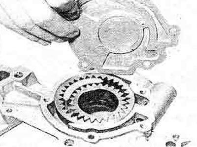
18.31A. Removing the oil pump cover
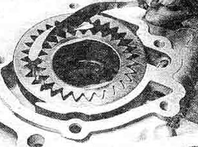
18.31B. Measuring the gap between the internal gear and the crescent
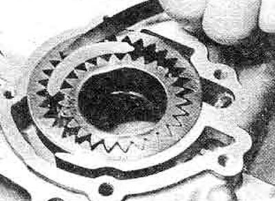
18.31C. Measuring the gap between the outer gear and the crescent
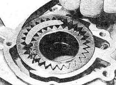
18.31D. Measuring the clearance between the external gear and the pump body
- The inner star to the crescent moon
- The outer star to the crescent moon
- Outer sprocket to the housing
32. If the measurements are satisfactory, measure the play of the mechanism using the feeler blade (photo). The play should be within the specified tolerance.
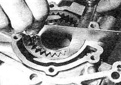
18.32. Measuring the external clearance of gears
33. If any of the measurements are outside the tolerance, the oil pump must be replaced completely.
34. Pressure regulator components rarely fail, but if they do, remove the cap and replace all valve components. Replace the pump seal (photo).
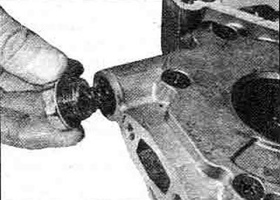
18.34A. Remove the pressure regulator cover - note the sealing gasket...
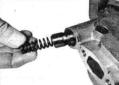
18.34B.... remove the adjusting spring and valve
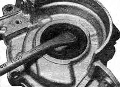
18.34C. Removing the oil pump seal
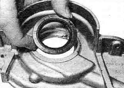
18.34D. Seals shall be renewed each time after removal
35. With the oil filter removed, check the pressure relief valve (photo).
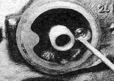
18.35. Checking the oil pressure relief valve
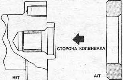
Figure 1.35. Installation details of the crankshaft guide bearing bushing
36. On Turbo and 2.0 liter automatic models there are two similar valves in the oil cooler support. They also need to be checked.
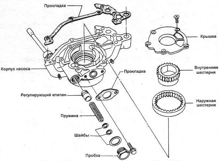
Figure 1.36. Oil pump components
Cylinder Head Components
37. Look Chapter 17.
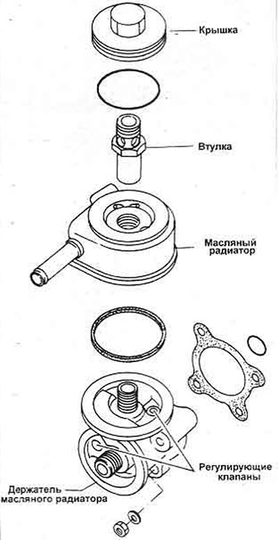
Figure 1.37. Oil cooler components - fitted to 2.0 liter automatic and early Turbo
Seals and gaskets
38. It is recommended that all gaskets and seals be replaced during an engine overhaul.