


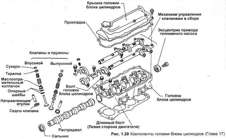
2. Unscrew the bolts gradually, in two stages, remove the valve assemblies from the cylinder head.
3. Remove the spark plugs.
4. Lock the camshaft with a homemade tool (Figure 1.30), unscrew the camshaft toothed pulley bolt and the fuel pump cam guide plate bolts. Remove the toothed pulley and the fuel pump cam plate.
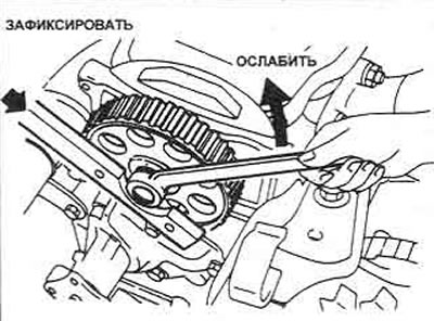
Figure 1.30. Locking the camshaft toothed pulley
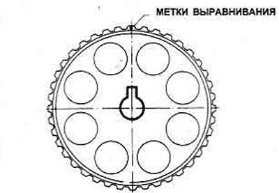
Figure 1.31. Camshaft toothed pulley key and alignment marks
5. Remove the camshaft and oil seal.
6. Remove the valves and associated components.
7. To remove the springs you will need a valve spring puller.
8. If a tool is not available, temporarily install the valve rocker shafts, press on the rocker arm to compress the valve spring, using the back of the shafts as a fulcrum.
9. Compress the first valve springs, remove the lock crackers.
10. Gently release the puller, remove the spring retainer, valve springs and spring seats, remove the oil seal.
11. Remove the valve and store it with the components in numbered sequence so that they can be reassembled in their original position (photo).
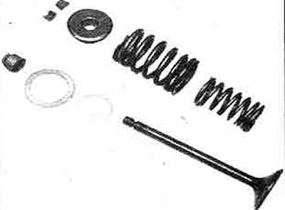
17.11 Valve components - in order of assembly
12. Remove the remaining valves.
13. Clean the cylinder head surface from carbon deposits in the combustion chambers and channels. The valve head, valve stems and valve guides must also be cleaned from carbon deposits. Wash the combustion chambers and channels.
14. If the engine is installed in a vehicle, clean the pistons and the top of the engine cylinders.
15. To prevent carbon deposits, the piston head can be polished.
16. Check the valve heads for corrosion and burns, especially the exhaust valve heads. If the pitting on the valve and seat is small, it can be removed by grinding, then the valves must be lapped.
17. If the valve seat is corroded, it is necessary to turn them and install new valves. It is better to entrust this work to a specialist.
18. The valves are ground in the following manner. Apply a coarse paste to the contact surfaces of the valve and the seat, insert the valve into the guide. Place a rod with a suction cup on the valve head and grind the valve manually in half a turn, holding the rod between the palms of your hands. When the paste stops working, remove the valve and repeat the procedure until you get a uniform matte gray surface on the bearing surface of the head and the valve seat. Then repeat the process using a fine grinding paste. Carefully remove the remains of the lapping paste, being careful not to let it get into the channels or into the valve guides. Wipe the valves and seats with a rag.
19. Check the valve springs. If any spring is broken (deformed), all springs must be replaced. Compare the free-release height of the old springs with the new ones. If some springs are not within specifications, replace them.
20. The oil supply holes in the rocker arm posts must be clean.
21. The cylinder head can be checked for surface distortion by placing it on a piece of glass plate or using the edge of a feeler gauge blade. If there is non-flatness or if the cylinder head surface is corroded, it must be treated or replaced.
22. Check the camshaft bearings for wear. If there is wear, the cylinder head must be replaced, as the bearings are drilled right into it.
23. Do not make any marks on the camshaft.
24. Check the camshaft cams; if there is wear, the shaft must be replaced.
25. Check the valve clearances in their guides. If there is a lot of play, the guides must be replaced. This work must be done in a specialized workshop, since the cylinder head must be heated to remove the guides. The new guides must protrude 10.2-10.4 mm above the cylinder head and then be expanded to 7.000-7.018 mm.
26. Use new valve stem seals.
27. Start assembly from the first valve, lubricating it and inserting it into the guide (photo).
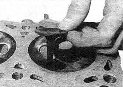
17.27. Installing the valve
28. Install the inner and outer spring seats, the oil seal, and the inner and outer springs so that their longer coils are directed toward the head. Install the spring retainer (photo).
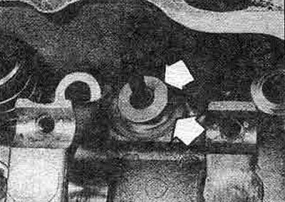
17.28A. Installing the inner and outer valve spring plates...
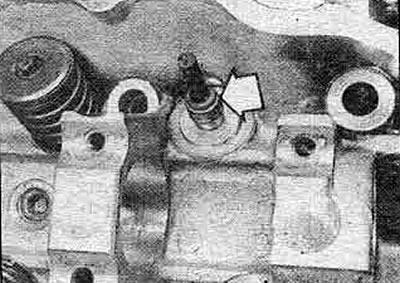
17.28V.... new oil seal
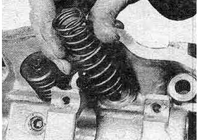
17.28C. The outer ends of the valve spring, painted, are directed upwards
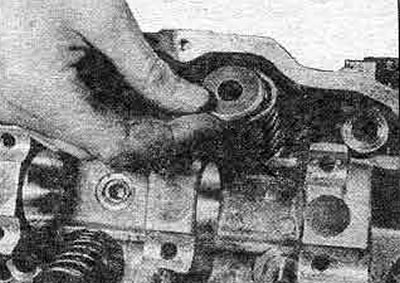
17.28D. Valve spring retainer
29. Compress the valve springs, insert the valve lock crackers (photo).
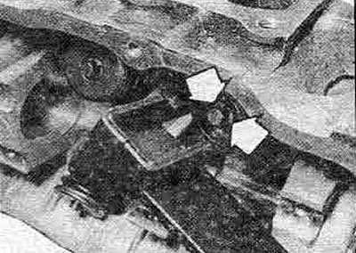
17.29D. Valve spring compression (valve lock crackers are marked with arrows)
30. Smoothly release the spring compressor, check the correct installation of the crackers.
31. Install the remaining valves in the same way.
32. To install the valve components, lightly tap the end of each valve stem with a hammer.
33. Lubricate the camshaft bearings, insert the camshaft into the head.
34. Install the fuel pump cam mounting plate and tighten the bolt. Install a new camshaft oil seal (photo).
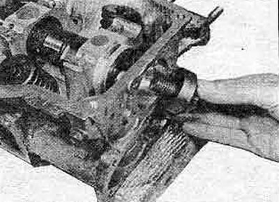
17.34 Installing the fuel pump cam on the camshaft
35. Install the camshaft timing pulley and tighten the bolt to the tightening torque specified in Specifications. Rotate the pulley, setting the alignment mark on the frame at 12 o'clock. The cam of cylinder No.1 should be directed downwards, towards the cylinder head.
36. Before installing the valve mechanism, check the wear of the shafts and rocker arms. Replace worn components.
37. The intake rocker shaft is marked at one end with two cuts (Figure 1.32). This end of the shaft should be directed towards the timing belt. The exhaust rocker shaft is unmarked.
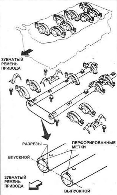
Figure 1.32. Rocker arm assembly parts
38. The marks on the ends of the shafts should be at the top. These marks indicate the location of the lubrication holes of the valve rocker shaft.
[Data copied from web resource: NISSANBOOK]
39. Assemble each rocker shaft (photo).
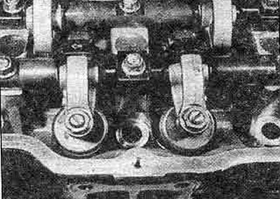
17.39. The arrow on the spring points towards the toothed belt drive
40. Unscrew the rocker arm adjuster screws completely, attach the valve mechanism to the cylinder head with bolts. Tighten the shaft bolts evenly in 2-3 stages (Figure 1.33), placing the cylinder head on blocks, since some valves will open.
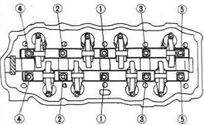
Figure 1.33. Valve rocker shaft bolt tightening sequence
41. Check that the camshaft sprocket is positioned so that cylinder #1 is at TDC on the compression stroke (item 35). Install the spark plugs.