


Table of contents: General information ↓ Examination ↓
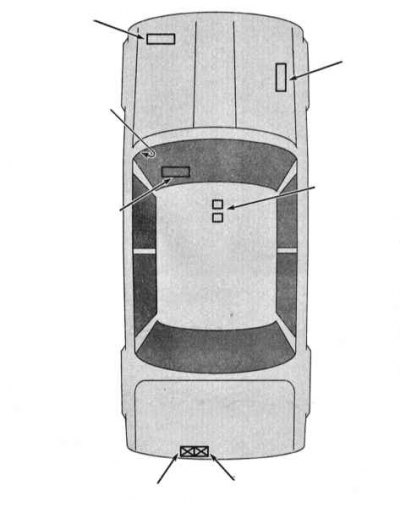
Relay location diagram on a car
General information
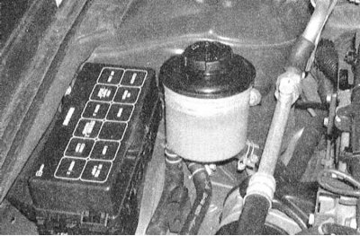
Relays are used to supply power or a control signal to some of the electrical consumers in the car (such as fuel injection system components, horn, starter, cooling fan(s), fog lights, etc.). In fact, a relay is an electric key that ensures the closure of the high-voltage circuit by a low-voltage signal. If a relay fails, the corresponding consumer will not function. Most relays are located in two mounting blocks located in the engine compartment, while others are scattered around the car. A description of how to check the proper functioning of a relay is given below. Failed relays must be replaced.
 |
 |
Examination
1. If you cannot figure out how to connect the relay to the corresponding electrical circuit using the electrical connection diagrams, you should remember that the approach to checking any relay is basically the same in all cases (see below).
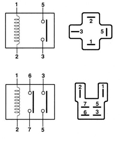
2. The Maxima models covered in this Manual use four basic types of relays. Some of them are normally closed, others are normally open, and the third and fourth polygons contain both normally closed and normally open types.
 |
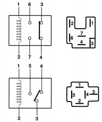 |
4. Usually, the control circuit is always connected to two of the relay contact terminals. When low-voltage voltage is applied to these terminals, the current begins to circulate through the relay control winding, which results in the closing of the large contacts of the working circuit of the consumer of electric power. The remaining terminals are the terminals of the working (high-voltage) circuit.
5. To facilitate identification of the relay terminals, explanatory markings with an image of the key connection diagram are usually applied to its body. If such markings are missing, you should refer to the electrical connection diagrams.
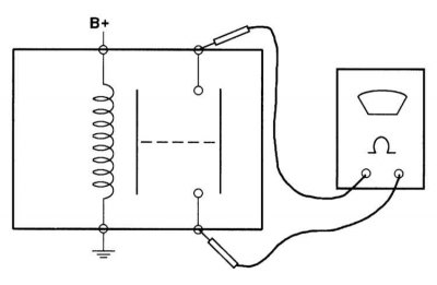
6. To check, connect an ohmmeter between the two terminals of the relay's high-voltage circuit. In the case of a normally open relay, there should be no continuity. Now connect a fused jumper wire between one of the relay's control terminals and the positive terminal of the battery. Using another jumper wire, ground the other control terminal - the relay should click, after which the ohmmeter will register the presence of continuity (normally open relay). Some relays require mandatory polarity of connection - if there is no click, try changing the polarity of the control terminals.
7. If the test result is negative, replace the relay.