


Table of contents: Examination ↓ Replacement ↓
Warning! The models of vehicles covered in this manual are equipped with a supplemental restraint system (SRS). Before performing any work near the air bag unit, steering column or instrument panel, turn off the SRS to avoid injury from accidental deployment (see section Airbags - General Information). The SRS circuit wiring is easily identified by the yellow color of the insulation.
Examination
1. Disable the additional security system.
2. Remove the driver's knee rest and steering column cover covers (see Chapter Body).
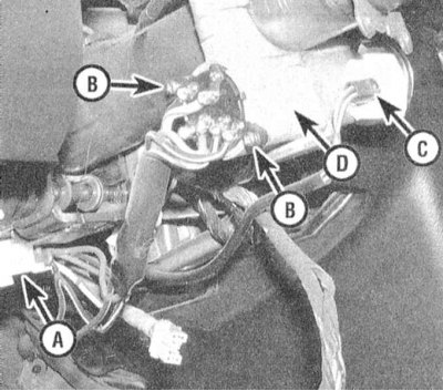
A - Electrical wiring connector
B - Mounting screws
C - Key buzzer connector
D - Lock cylinder housing
3. Disconnect the contact connector located approximately 15 cm below the switch.
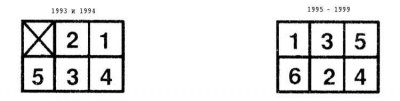
4. Using an ohmmeter, check the connector for continuity between the contact terminals in each ignition key position.
| Switch position | Presence of conductivity between the terminals |
| OFF (OFF.) | There is no conductivity |
| ACC (Parking) | 1 and 2 |
| ON (Ignition) (1993 and 1994) | 1, 2 and 3 |
| ON (Ignition) since 1995 | 1, 2, 3 and 4 |
| START (START) (1993 and 1994) | 1, 3, 4 and 5 |
| START (Launch) since 1995 | 1, 3, 5 and 6 |
5. If any abnormalities in conductivity distribution are detected, replace the switch.
6. Assess the degree of wear and reliability of the lock cylinder fixation. Make sure that the location of the index marks corresponds to the actual position of the key in the lock. If defects are detected, replace the lock assembly.
Replacement
1. Perform the procedures described in paragraphs 1 through 3 to gain access to the ignition switch.
Information copied from the portal (NissanBook)
2. Disconnect the contact connector, unscrew the mounting screws and remove the switch together with the section of the wiring harness.
3. Installation is carried out in reverse order.
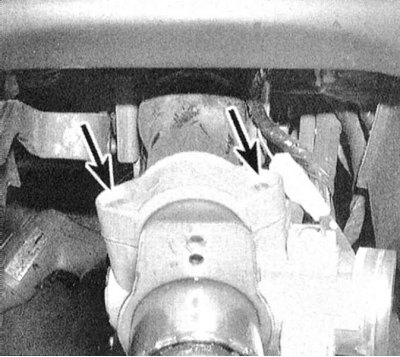
4. It is not possible to replace the lock cylinder individually. If defects are detected, the entire ignition lock assembly should be replaced. Remove the shear bolts securing the assembly (use a drill and a special extractor), split the support bracket in half and remove it from the steering column.
5. Install a new switch in place of the faulty one, screw in new bolts and tighten them until the heads are sheared off. If the vehicle is equipped accordingly, do not forget to put the airbag spring contact back in place, only then install the steering wheel (see Chapter Suspension and steering).