Warning! The car models covered in this manual are equipped with an additional security system (SRS). Disable the SRS before doing any work near the airbag unit, steering column, or instrument panel to prevent injury from accidental deployment. SRS circuit wiring is easily identified by the yellow color of the insulation.
Switches mounted in the trim panel of the instrument cluster
1. Disable SRS. Several switches are mounted in the instrument cluster trim panel. To the left of the steering column are the switches for controlling the functioning of the electric drive of rear-view mirrors, the main switch of the tempostat (On off), and (with appropriate vehicle equipment) anti-theft warning lamp and fog light switch. To the right of the steering column there is a knob for adjusting the intensity of instrument illumination and on models 1993 and 1994. issue) alarm switch. On models since 1995, no. the alarm switch is placed in the central part of the panel.
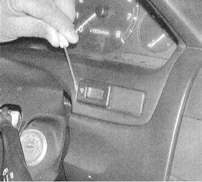
2. Each of the switches can be removed from the front of the panel by prying with a screwdriver. Note: To avoid damage to the panel, wrap the tip of the screwdriver with tape. Simple switches, such as the fog light switch, should only show continuity between the 2-pin connector terminals when the ignition is on. Between the terminals of the 3-pin control switch, the illumination intensity of the instruments must be conductive in any position of the ignition key other than OFF.
3. After releasing the switch from the panel, disconnect the electrical wiring from it.
4. Check up correctness of distribution of conductivity between plugs of a socket. Replace defective assemblies.
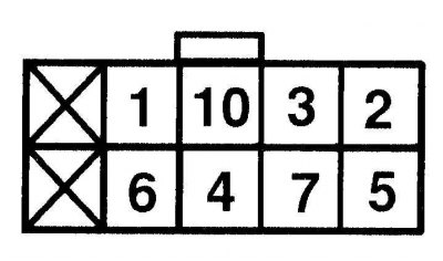
| Switch position | Conductivity between terminals |
| OFF (off) | No conductivity |
| right | 1 and 2 |
| Left | 2 and 3 |
| Up | 2 and 3 |
| Down | 1 and 2 |
| Mirror heating | 1, 3 and 10 |
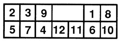
| Switch position | Conductivity between terminals |
| OFF (off) | No conductivity |
| Left mirror right | 1 and 2, 6 and 3 |
| left mirror left | 2 and 3, 1 and 6 |
| Left mirror up | 2 and 3, 1 and 7 |
| Left mirror down | 1 and 2, 3 and 6 |
| Right mirror right | 1 and 2, 3 and 4 |
| Right mirror left | 2 and 3, 1 and 4 |
| Right mirror up | 2 and 3, 1 and 5 |
| Right mirror down | 1 and 2, 3 and 5 |
5. Installation is carried out in the reverse order.
Switches of the central facing section of the instrument panel
1. Disable SRS. On the central facing section of the instrument panel there is an alarm switch, a clock and a switch for heated rear window (models since 1995 issue.).
2. Remove trim panel (see chapter Body).
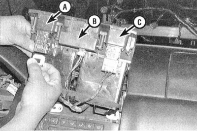
3. Having separated facing section from the panel of devices, disconnect the electroconducting brought to the components built in it. The components are attached to the panel with screws. The test can be carried out without removing the elements.
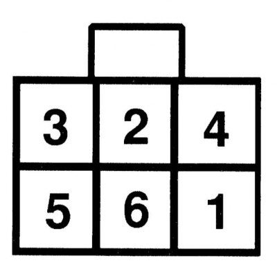
4. Refer to the wiring diagrams for the distribution of conductance between the switch connector terminals.